Microcontroller-Based
Single Knob Tuning for Satellite Operations
with Doppler Correction and Antenna Rotator Interface
I am a latecomer to the ham
radio satellites interest. In June 2023, a friend1
told me about having made contacts by way of the
Russian satellite RS-44.
I had known about the International Space Station’s FM transponder, and
had read about ‘Oscar’ satellites, but was not previously aware of a
Russian ham radio
satellite. The idea seemed exotic and
I wanted to try it myself. My friend assured me that this could be done
using a VHF/UHF capable transceiver and inexpensive Arrow antenna—actually
two antennas on one boom, with an optional built-in (low power)
duplexer.
Satellite communication
appeals to hobbyists in different ways. Hams who design, construct and
manage deployment of the
amateur satellites obviously have strong
engineering interests and abilities. For myself, I wanted to
make just one contact on that Russian satellite for the thrill of doing
so. However, it did not take long to realize that there is a lot to
learn, just to achieve the most basic level of satellite operating
proficiency.
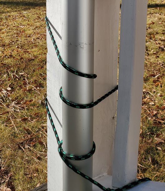 The Arrow antenna was delivered within a few days. I mounted it at a
fixed elevation angle to a short mast, at first on a portable stand,
and later lashed with ropes to the bottom post of the back porch steps.
I disconnected the duplexer and substituted
separate coax runs to the 2 meter and 70 centimeter shared-boom
antennas. The
azimuth rotator was my wife N4EFS, who endured the blazing South
Carolina summer sun to turn the antenna by hand while I attempted to
make a first contact on RS-44.
The Arrow antenna was delivered within a few days. I mounted it at a
fixed elevation angle to a short mast, at first on a portable stand,
and later lashed with ropes to the bottom post of the back porch steps.
I disconnected the duplexer and substituted
separate coax runs to the 2 meter and 70 centimeter shared-boom
antennas. The
azimuth rotator was my wife N4EFS, who endured the blazing South
Carolina summer sun to turn the antenna by hand while I attempted to
make a first contact on RS-44.
 Many ham radio satellite operators use the excellent computer program
SatPC32, which (among other features)
displays the continuously changing bearing to a selected satellite. As the
satellite crosses the sky its current azimuth can
be read by eye
from
the bottom left corner of SatPC32’s
main screen. I installed the program but did not interface it with the
rigs, or directly to the human rotator. Nevertheless, using this
limited setup we were able to
make CW QSOs with
a few patient operators.
Many ham radio satellite operators use the excellent computer program
SatPC32, which (among other features)
displays the continuously changing bearing to a selected satellite. As the
satellite crosses the sky its current azimuth can
be read by eye
from
the bottom left corner of SatPC32’s
main screen. I installed the program but did not interface it with the
rigs, or directly to the human rotator. Nevertheless, using this
limited setup we were able to
make CW QSOs with
a few patient operators.
During this exploratory phase of operating I
could also hear single sideband (SSB) stations, and make their audio
intelligible for short periods by continuously
hand-tuning the
receiver VFO. There was no chance of making an SSB contact at this
stage. For successful SSB communication it would be necessary to
implement automatic Doppler frequency correction. To reiterate, the
computer was not interfaced with either the Icom
IC-7100 transmitter or
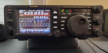
Yaesu FT-991A receiver.
RS-44 is an inverting
linear ‘bird’ (the fraternal nickname
for satellite). ‘Inverting’ means that uplink and downlink
frequency
ranges are mirror reflected. The bottom end of
the uplink band, a 60 KHz patch of the 2 meter band, maps to the top
end of the downlink band, a same-sized chunk of
the 70 centimeter ham band. Zero-beating
a received station can be challenging—It is necessary to be able to
hear one’s transmit signal from the satellite, and to be sure that it
isn’t artifact. If the received carrier tone changes pitch, reflecting
the
Doppler effect, it is a true signal. For zero-beating it is helpful to
start tuning somewhere in the ballpark of the target frequency.
Figuring out where to tune the receiver in order to hear the
transmitter led me to the idea of using a rotary encoder to tune both
transmitter and receiver synchronously. A single knob could tune the
two rigs in opposite directions, in a sense mimicking ordinary simplex
tuning. It would still be necessary to adjust the actual transmit and
receive VFOs
for the
Doppler effect.
 I began to think about a microcontroller-based device that could
support both one-knob linked tuning and also Doppler correction of
transmit and receive frequencies. Although only a few months have
elapsed since this concept began to form, I am no longer sure of
the order in which early parts of the plan came together. One
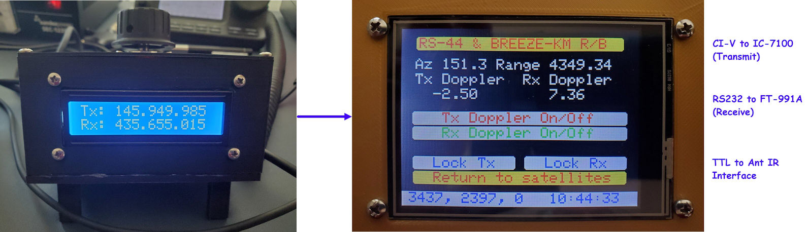
decision was to use a two-line LCD to display uncorrected but linked
transmit and receive frequencies (see photo at top of page). For the
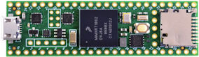
microcontroller I thought of using a WiFi enabled board such as an
ESP8266, but hesitated and instead selected the Teensy 4.1, which has a
built-in microSD card slot that could be used for storing satellite and
station parameters. Teensy 4.1 also has an integral real time clock,
which would be convenient for computing time-dependent satellite
parameters. I had recently used this particular
development board
in a couple of other projects and was familiar with its basic
documented capabilities.
I began to think about a microcontroller-based device that could
support both one-knob linked tuning and also Doppler correction of
transmit and receive frequencies. Although only a few months have
elapsed since this concept began to form, I am no longer sure of
the order in which early parts of the plan came together. One
decision was to use a two-line LCD to display uncorrected but linked
transmit and receive frequencies (see photo at top of page). For the
microcontroller I thought of using a WiFi enabled board such as an
ESP8266, but hesitated and instead selected the Teensy 4.1, which has a
built-in microSD card slot that could be used for storing satellite and
station parameters. Teensy 4.1 also has an integral real time clock,
which would be convenient for computing time-dependent satellite
parameters. I had recently used this particular
development board
in a couple of other projects and was familiar with its basic
documented capabilities.
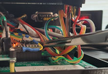
One of these previous Teensy 4.1 projects involved a
custom PCB that had extra solder pads and traces that were not required
by the
original project. Extra connection points might be handy for future
experimentation. The
future was now.
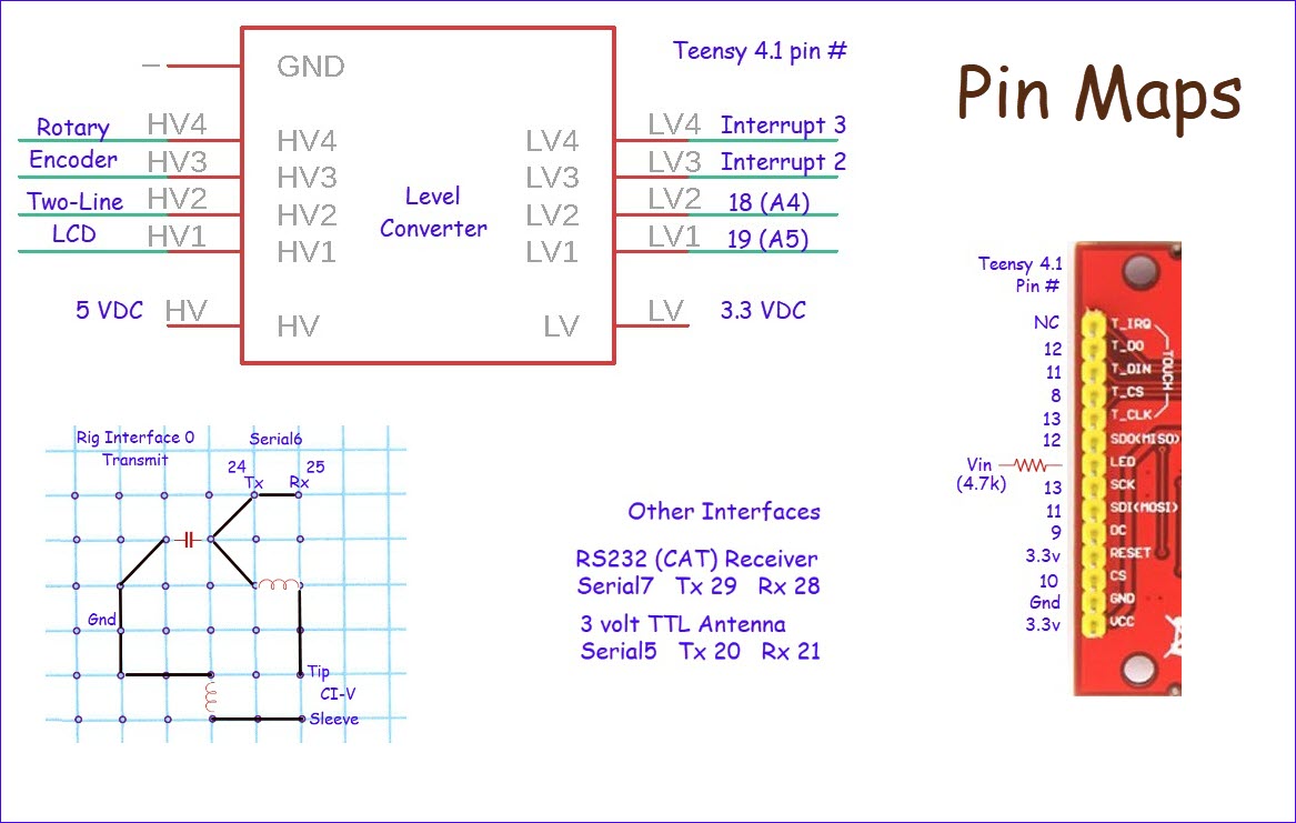
Interfacing the rotary encoder and LCD was
relatively simple, the only potential ‘gotcha’ being that rotary
encoder pulses are minimally 5 volts and Teensy 4.1 pins are not 5-volt
tolerant. Thus encoder pulses had to be converted to 3.3 volts for
connection to the microcontroller. The particular rotary encoder used
for the project (this one)
had a long cable attached, much longer than needed, so I cut it in half
and used the other half for the LCD, which had an integral 4-pin i2c
connector. I tested the
two-row LCD at 3.3 volts but
found that for satisfactory brightness and contrast it also needed 5
volts.
Under ‘Other Interfaces’
in the ‘Pin Maps’ figure (above)
there is an entry for a 3 volt TTL Antenna rotator interface. That
interface was added after the
linked tuning and
Doppler components, and is described as a separate story on this page.
 Displayed frequencies are just numbers. It is possible to demonstrate
linked ‘tuning’ without tuning anything, a simulation if you will.
After completing such an exercise I began to address interfacing the
transceivers for actual VFO control. The Yaesu FT-991A, which serves as
receiver in the setup has
a DB9 jack on its back panel for either CAT or GPS. In an
earlier project the transceiver was
successfully interfaced with an ESP8266 using an RS232 to TTL adapter, so the same adapter was
selected for this project. A manufactured DB9 male
to DB9 female cable connects the Yaesu transceiver to the adapter.
Displayed frequencies are just numbers. It is possible to demonstrate
linked ‘tuning’ without tuning anything, a simulation if you will.
After completing such an exercise I began to address interfacing the
transceivers for actual VFO control. The Yaesu FT-991A, which serves as
receiver in the setup has
a DB9 jack on its back panel for either CAT or GPS. In an
earlier project the transceiver was
successfully interfaced with an ESP8266 using an RS232 to TTL adapter, so the same adapter was
selected for this project. A manufactured DB9 male
to DB9 female cable connects the Yaesu transceiver to the adapter.
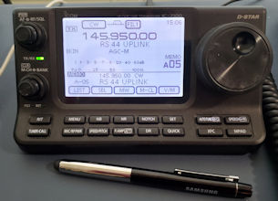
The Icom IC-7100 has a 3.5 mm jack labeled ‘Remote’
on its back panel. This jack exposes the Icom 2-wire CI-V bus, data on
tip, and ground on sleeve. CI-V level is 3 volts, so nothing
special was needed for that. At some time in the past Icom had a
CI-V to RS232
interface device called CT-17 (no longer available). On examining the
CT-17 documentation I saw that in addition to an RS232-to-TTL chip, the
circuit included a capacitor and a couple of inductors (RF filtering).2 For prudence’s sake I included
these when interfacing Teensy 3.3 volt
serial to the Icom bus. The graphical representation of the CI-V
interface in the lower left
corner of the ‘Pin Maps’ illustration represents a small cut piece of
prototyping circuit board.
The
cable is a standard stereo headphone cable, with no connection to
the ring from the jack.
The software side of these rig interfaces evolved
over time, with the addition of Doppler correction
and other features. The specific Teensy serial channels used and other
details are documented in the ‘Pin Maps’ illustration,
and can also be deduced from the source code, which will be posted and
linked from near the bottom of this page. The main consideration was to
select
pins that were not needed for the Touch Screen (‘Pin
Maps’ illustration) and that preferably had
solder traces on the repurposed PCB, for easy connection.

One important software detail concerns how
frequencies to be tuned for each satellite are specified. For testing,
I
hard-coded pseudo band boundaries and
twiddled the tuning knob to observe changing frequencies, but
hard-coding the band edges would not
do for practical deployment. I confess to not having used XML or any
standard way of specifying parameters. Instead, a plain text file
records transmit and receive frequencies for the satellites of
interest.
Each record starts with
the satellite name as given in the TLE file. An
example entry is shown above.
After the satellite name, each line of text consists of tab-delimited
data: transmit left boundary, <tab> transmit right boundary
<tab> receive left boundary <tab> receive right boundary,
and then optionally preferred starting frequencies, i.e. where in the
band the tuning dial should be set at the beginning of a satellite
pass.
If not otherwise specified, tuning starts in the middle of the band.
For FM satellites the left and right bounds generally specify the same
frequency. There is no need for tuning the receiver when Doppler
correction is in effect and only one frequency is used.
 On to the Doppler problem... I had only a superficial understanding of
what programs like SatPC32
do internally. I knew how to compute Doppler-shifted frequency from a
source
frequency and velocity.3 I also knew that
Keplerian ‘Two-Line Elements’
or TLEs need to be refreshed fairly often in order for
programs like SatPC32 or Orbitron or similar applications to predict
satellite passes and compute their orbits
accurately. But I had no idea how these programs
do what they do, and imagined that the algorithms must be complicated.
On to the Doppler problem... I had only a superficial understanding of
what programs like SatPC32
do internally. I knew how to compute Doppler-shifted frequency from a
source
frequency and velocity.3 I also knew that
Keplerian ‘Two-Line Elements’
or TLEs need to be refreshed fairly often in order for
programs like SatPC32 or Orbitron or similar applications to predict
satellite passes and compute their orbits
accurately. But I had no idea how these programs
do what they do, and imagined that the algorithms must be complicated.
 To get some sense of how to proceed I started reading about the
‘two-body’
problem, struggling to understand the relevant mathematics
and not succeeding! Then came a breakthrough. At some point in my
research the realization hit
that satellite orbit prediction programs were not solving for orbit
parameters at the application level themselves, That
problem had been
solved long ago, and encapsulated in such a way that programs had
only to invoke canned library functions. Forget orbit formulas and
their underlying math and physics—well these are good subjects to
learn, but
are not essential for writing a program or constructing a device to
tune the radio
or
rotate the antenna.
To get some sense of how to proceed I started reading about the
‘two-body’
problem, struggling to understand the relevant mathematics
and not succeeding! Then came a breakthrough. At some point in my
research the realization hit
that satellite orbit prediction programs were not solving for orbit
parameters at the application level themselves, That
problem had been
solved long ago, and encapsulated in such a way that programs had
only to invoke canned library functions. Forget orbit formulas and
their underlying math and physics—well these are good subjects to
learn, but
are not essential for writing a program or constructing a device to
tune the radio
or
rotate the antenna.
Algorithms and implementing software for
predicting positions and velocities of satellites in conjunction with
the TLEs are referred to collectively by the
label SGP4. Programs that were
originally published decades ago have
been extended and refined and ported to multiple programming languages
and computing platforms. One of these platforms (thanks to SparkFun)
is the Arduino IDE, which I use for nearly all microcontroller
programming. The SparkFun Arduino port of SGP4 comes with a couple of
easy-to-follow examples. These examples illustrate how
to initialize the model for a specific satellite by supplying the
relevant Keplerian two-line elements and our earth station location
(latitude, longitude and altitude).
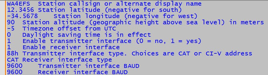
 Thus, another text file! Each row of the station.txt file starts with a
parameter value, then optionally <tab> description. SGP4
requires universal time (UT) for its computations, so it is
necessary to convert Teensy time to UT. Teensy time is whatever time
zone
has been set, possibly also including the cursed Daylight Saving Time
(DST) adjustment. The real time clock’s internal format is a signed
count of the number of
seconds from January 1, 1970, a number that will overflow
in 2037. Therefore, it is pointless to worry about DST after year 2037.
By the way, the SGP4
Arduino library code understands British Summer Time, which ends on a
different
day than United States DST. Argh!
Thus, another text file! Each row of the station.txt file starts with a
parameter value, then optionally <tab> description. SGP4
requires universal time (UT) for its computations, so it is
necessary to convert Teensy time to UT. Teensy time is whatever time
zone
has been set, possibly also including the cursed Daylight Saving Time
(DST) adjustment. The real time clock’s internal format is a signed
count of the number of
seconds from January 1, 1970, a number that will overflow
in 2037. Therefore, it is pointless to worry about DST after year 2037.
By the way, the SGP4
Arduino library code understands British Summer Time, which ends on a
different
day than United States DST. Argh!
It would be possible to initialize the Teensy
real-time
clock to
UT and ignore DST, but many users (myself included) are more
comfortable scheduling their radio operating time by wrist watch or
wall clock.
Another option would be to move to Hawaii, where it is summer nearly
all
the time and there is no need for DST. The way in which the
microcontroller code handles DST is currently in flux. I made a table
of start and end times for the present through year 2037, but have not
fully implemented this approach.
 This project story is not intended to be a ‘How to’, although
sufficient
detail
is included to support reproducing essential features of the project.
Pin numbers
for interfacing both internal and external components are identified
redundantly in the ‘Pin Maps’ illustration and sketch. Additionally,
the required
parameter files TLEs (e.g. amateur.txt), frequencies.txt and
station.txt have been described. Updating TLEs requires an extra step
as TLEs cannot be directly downloaded to the device (at present).
Instead the TLEs file must be copied to a microSD card.
This project story is not intended to be a ‘How to’, although
sufficient
detail
is included to support reproducing essential features of the project.
Pin numbers
for interfacing both internal and external components are identified
redundantly in the ‘Pin Maps’ illustration and sketch. Additionally,
the required
parameter files TLEs (e.g. amateur.txt), frequencies.txt and
station.txt have been described. Updating TLEs requires an extra step
as TLEs cannot be directly downloaded to the device (at present).
Instead the TLEs file must be copied to a microSD card.
Removing and
inserting the microSD card requires minor surgery. My particular
3D-printed project
‘enclosure’ is open on the front and right-hand side, so forceps can be
used to access the card slot. It is neither
necessary nor
desirable to clamp or lock the forceps—a minimal grip suffices!
However,
the unit should be powered-down when
removing or inserting a card. The illuminated LED in the staged
photo (right) is misleading. Powering down the device may be considered
analogous to
administering anesthesia.
By convention, lower sideband is used below 20
meters, while upper sideband is used on 20 meters and above. However,
because inverting linear satellite uplink and downlink bands are mirror
images, all signals received
by the satellite
are inverted when retransmitted, in effect causing the
downlink sideband to be opposite to the uplink sideband. Thus
lower-sideband should be used for uplink, whether VHF or UHF, in order
to be received as upper sideband on the downlink band. Ham radio
transceivers typically default to the aforementioned convention.
Therefore
it may be necessary to change the transmit mode explicitly to lower
sideband for
satellite transmission.
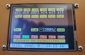 With mirror-image tuning of uncorrected transmit and receive
frequencies, along with Doppler correction of both VFOs, my single
sideband transmit frequency was approximately –1200 Hz from the
frequency that I was trying to zero-beat, for example an SSB station
calling CQ. This value was ascertained experimentally. I first tuned
the receiver to an inactive test frequency, then
unplugged the transmit interface and tuned the transmitter (using the
rig’s main tuning dial) from its Doppler
corrected frequency to the zero-beat frequency as quickly as
possible, making note of the delta.
This ‘experiment’ was repeated at a small number of different test
frequencies until I felt confident of the
delta value (to an acceptable approximation). It is challenging to make
such observations when Doppler
is changing rapidly. I have heard other stations transmit long streams
of Morse dots, probably for the same purpose.
With mirror-image tuning of uncorrected transmit and receive
frequencies, along with Doppler correction of both VFOs, my single
sideband transmit frequency was approximately –1200 Hz from the
frequency that I was trying to zero-beat, for example an SSB station
calling CQ. This value was ascertained experimentally. I first tuned
the receiver to an inactive test frequency, then
unplugged the transmit interface and tuned the transmitter (using the
rig’s main tuning dial) from its Doppler
corrected frequency to the zero-beat frequency as quickly as
possible, making note of the delta.
This ‘experiment’ was repeated at a small number of different test
frequencies until I felt confident of the
delta value (to an acceptable approximation). It is challenging to make
such observations when Doppler
is changing rapidly. I have heard other stations transmit long streams
of Morse dots, probably for the same purpose.
The frequency discrepancy may have a
simple
explanation—I don’t know.
In any
case, the problem was addressed empirically by making provision for a
signed correction to be applied to either transmit or receive VFO, or
apportioned to both. I had no evidence as to which VFO should be
adjusted, but entered
the correction
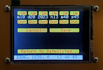
for the transmit frequency. That can be changed, of course. When a
value for the correction is entered or changed (‘Tools’
screen photo above left) the adjusted value is automatically stored in
EEPROM and
restored
when the device is restarted. The correction does not apply to
single-frequency transponders (e.g., FM satellites). If a correction is
needed there, it can be made in the frequency file. However, it is not
generally necessary to adjust the transmit frequency when working an FM
satellite.
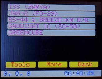 The satellite selection screen (main screen) has room for eight or
nine
satellite names. Buttons labeled ‘More’ and ‘Back’ in the photo were
planned for
paging through a longer list of names. However, the paging function has
not (yet) been implemented, chiefly because there are not a great many
active ham radio satellites, or hours in the day to pursue them. Note,
for example, the small number of chiefly blue rows on the AMSAT
Status Page.
The satellite selection screen (main screen) has room for eight or
nine
satellite names. Buttons labeled ‘More’ and ‘Back’ in the photo were
planned for
paging through a longer list of names. However, the paging function has
not (yet) been implemented, chiefly because there are not a great many
active ham radio satellites, or hours in the day to pursue them. Note,
for example, the small number of chiefly blue rows on the AMSAT
Status Page.
My home bench projects are never completely
finished.
They reach stable points, where they are either used or set aside while
ideas percolate. The current microcontroller code version 1.1
may be considered a source of ideas for similar projects. The rig
interfaces are specific to my personal use (Icom transmitter and Yaesu
receiver) but could be adapted or generalized to work with other ham
radio transceivers. The posted sketch was developed with Arduino IDE
2.2.1. Of course, #include libraries listed near the top of the sketch
are required for successful compilation.

 Addendum 1:
In truth, the surgical method of removing and inserting a microSD card
for TLE updates was not ideal. Much better would be to expose the
card slot externally, as it would normally be on a consumer device.
Doing this turned out to be a snap, using a microSD to microSD
extension cable, 15 cm in length (longer than needed). I had no idea
such a thing exists, but found one here (photo left). However, this improvement was
soon superseded by another.
Addendum 1:
In truth, the surgical method of removing and inserting a microSD card
for TLE updates was not ideal. Much better would be to expose the
card slot externally, as it would normally be on a consumer device.
Doing this turned out to be a snap, using a microSD to microSD
extension cable, 15 cm in length (longer than needed). I had no idea
such a thing exists, but found one here (photo left). However, this improvement was
soon superseded by another.
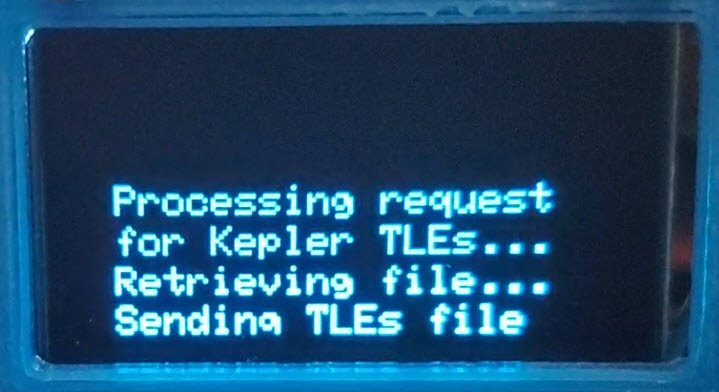
The Teensy 4.1 does not have built-in WiFi
capability, however, several ESP8266 WiFi-enabled boards were on-hand
and available to use. Why not just add another microcontroller to the
project? —There was room in the enclosure, though just barely! It
seemed wasteful, in a way, to dedicate an ESP8266 to the sole purpose
of updating TLEs, so I thought of something else to do with it. In
addition to making the WiFi connection needed for downloading TLEs
directly from the Internet, the ESP8266 could also be used to display
satellite passes diagrammatically, as some computer tracking
applications do. This whole story will have to be told on a future
project page. For the present I remark that the microSD extension was
nice to have for about one week after installation, whereupon it was no
longer needed!
Demo video: Sat Helper
Endnotes
1. AL7JX Glen Fuller
2. Inductor values
specified in the CT-17 schematic diagram
are 1 μH and the capacitor is 100
pF.
3. If the satellite’s
distance from the station (range) is obtained once per second then the
distance traveled in one second is equal to the difference between two
successive range computations. Velocity is directed (signed) distance
divided by
time.
Let v
stand for the satellite’s velocity with respect to the station, and C stand for the speed of light in
meters per second. The Doppler corrected frequency is the uncorrected
frequency multiplied by C/(C+v).
Project descriptions
on this page are intended for entertainment only.
The author makes no claim as to the accuracy or completeness of the
information presented. In no event will the author be liable for any
damages, lost effort, inability to carry out a similar project, or to
reproduce a claimed result, or anything else relating to a decision
to use the information on this page.