Digital
to
Analog Converter: Microcontroller applications often use
an
analog to digital converter (ADC) for this or that feature. The
present project sprang from a desire to learn about the
opposite and less commonly encountered type (or direction) of signal
conversion. As initially
conceived, the goal was to exercise the tiny MCP4725
digital to analog (DAC) breakout board from
Sparkfun. However, around
the same time that I became interested in digital to analog conversion,
I acquired a couple of surplus microammeters . This
coincidence led to the thought of programming
the DAC to register values on the microammeter. In that way I could
become familiar with both devices at the same time.

Before doing anything with the microammeter I first tested the DAC
board following the guidance of Sparkfun’s Hookup Guide. This
tutorial demonstration produces a sine wave at about 4.5 Hz
(illustration
above). After the DAC ( and I ) passed this test, the plan for what to
do
next sort of evolved, and then side-slipped a bit.
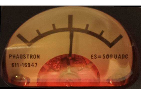 The microammeter was a center-zero type. Curiously its tick marks have
no annotations (numbers or units). However, small
print on the meter face says, “Phaostron 611-16947.”
Google search results suggested that the model may have once been used
as an aircraft
panel instrument.
The microammeter was a center-zero type. Curiously its tick marks have
no annotations (numbers or units). However, small
print on the meter face says, “Phaostron 611-16947.”
Google search results suggested that the model may have once been used
as an aircraft
panel instrument.
Through experimentation I found that the
meter backlight illuminates at 3 to 5 volts, and emits a warm red glow.
To display current flow in both directions, while at the same time
relying on the 0 to 5
volts analog output of the DAC, one side of the meter would need to be
fixed at
2.5
volts. To accomplish this I used two 1K resistors in series, as a
voltage divider, connecting the ‘common’
side of the meter to their midpoint.
DAC output would be coupled to the other side through a
current reducing resistor.
The MCP4725 is a 12-bit DAC. This means
it converts numbers between 0 and 4095 to a specified output
voltage
range, nominally 5 volts. Data (input values) are sent to the DAC
over i2c.
Arduino assigns analog pins 4 and 5 to
this serial bus,
as SDA and SCL respectively.
However, the fact that Arduino i2c
communication relies on analog pins has nothing to do with the fact that the DAC produces an
analog signal
from the digital (numeric) values it receives.
A 4600 ohm resistor between the DAC
output and the microammeter results in almost full-scale responsivity,
with 0 volts (negative 2.5 volts with respect to ‘common’)
moving the
meter to
near the left mark, and 5 volts (+2.5) reaching to near the right.
At this point I had no specific real-world application in mind for the
meter—it could be put into service as an
S-meter, maybe.
However, I
thought as an exercise to send a sequence of random values to it via
the DAC. The
number π is random, so they say. Thus, converting digits of π
to evenly spaced values in the range 0 - 4095 should work. The
resulting Arduino
test sketch maps individual digits to this
12-bit range (i.e. 0 times 455 to 9 times 455), which
should produce corresponding analog outputs in the range
0 - 5 volts.
 On hooking
everything up and running the sketch, the meter behaved as expected,
but
not such that unannotated readings could be converted to digits
mentally as rapidly
as the meter position changed. To compound the challenge of inferring
values from meter indications, there was also some over swing and
settling whenever successive
digits were widely spaced. Therefore, I added a 7-segment LED display,
for side-by-side comparison with the meter.
On hooking
everything up and running the sketch, the meter behaved as expected,
but
not such that unannotated readings could be converted to digits
mentally as rapidly
as the meter position changed. To compound the challenge of inferring
values from meter indications, there was also some over swing and
settling whenever successive
digits were widely spaced. Therefore, I added a 7-segment LED display,
for side-by-side comparison with the meter.
No
sooner was the LED in place than I also
wanted to associate a
tone with each digit. This might have been the point at which the
project careened off the rails, as
there
was absolutely nothing to be learned from adding a
tone—I
had already exercised the Arduino tone() function in a previous
project. Nevertheless, having thought to do it, I added tones from
the key of C-major, with ‘0’
mapped to middle C, ‘1’
to D, etc. up to ‘9’
mapped to E an octave higher.
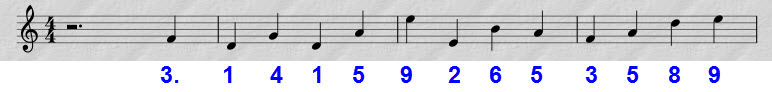
On listening
repeatedly to music-notes that correspond to a moderately short
random sequence, the sequence starts to sound
non-random. Well, obviously on repetition sounds can be anticipated,
hence lose their unexpectedness. I had slapped the first 756 digits
into the test sketch
(copied from one of the web pages that list many
thousands of digits).
Running through this many digits at the programmed timing takes just a
few
minutes, after which the sequence starts over from its
recognizable
beginning:
The preceding illustration is a little misleading
because the sequence of digits does not imply standard time, or a key,
or any music construct—it
is just a number.1 But
in listening to artificially associated tones and (crucially)
listening with repetition, the ear imposes patterns that convey the
illusion of
being present in the sequence itself.
Demo: Song of Pi
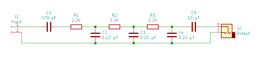
Loose
ends: The Arduino tone() function generates a square wave.
It is somewhat a matter of taste, but to me a square wave sounds harsh.
The smoothing filter was based on the one described here, but with component values
compatible with the range of tones produced by the DAC test sketch,
approximately 300 - 700 Hz (diagram below). After smoothing and
attenuation, the tone was amplified by an external audio amplifier
(Radio Shack #2771008).
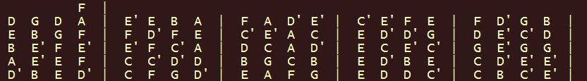
To improvise
chords requires being able to anticipate what sound is coming next (or
having committed the same to memory, which I have not!). For this trick
I wrote a simple function that converts digits to formatted note letter
names, assuming the key and timing context described above. Here are
the first few lines of output:
Apostrophes denote one octave up from
the base note of the same name.
Footnotes:
1. On
the other hand, π the
real number is said to contain every finite sequence, hence every
conceivable melody!
Project descriptions on this page are intended
for entertainment only.
The author makes no claim as to the accuracy or completeness of the
information presented. In no event will the author be liable for any
damages, lost effort, inability to carry out a similar project, or
to reproduce a claimed result, or anything else relating to a decision
to
use the information on this page.