 Playing the odds:
Suppose that four capacitors are randomly selected from a batch marked
1 nF at 10%, and are connected in series-parallel to make a circuit
having
the same 1 nF capacitance, as illustrated above. What would be the
appropriate tolerance designation for the 4-capacitor circuit? If the
individual capacitors are all 1 nF then the circuit capacitance is also
1 nF, but the σ value for a hypothetical batch of 4-capacitor circuits
will be the standard
error of the mean, denoted σm. To compute this
statistic, divide σ by √N. In this case N is 4 and √4 is 2 so σm
= σ/2. As previously noted, tolerance corresponds to 3σ
(i.e., tolerance is proportional to σ), which means that the tolerance
of the 4-capacitor circuit is the constituent capacitor tolerance
divided by 2, which in the example would be 5%. It is possible to
iterate the idea, so that 16 capacitors similarly configured would make
a circuit with 2.5% tolerance, and so forth, but that would be
silly—better to spend a dollar for a 1% capacitor.
Playing the odds:
Suppose that four capacitors are randomly selected from a batch marked
1 nF at 10%, and are connected in series-parallel to make a circuit
having
the same 1 nF capacitance, as illustrated above. What would be the
appropriate tolerance designation for the 4-capacitor circuit? If the
individual capacitors are all 1 nF then the circuit capacitance is also
1 nF, but the σ value for a hypothetical batch of 4-capacitor circuits
will be the standard
error of the mean, denoted σm. To compute this
statistic, divide σ by √N. In this case N is 4 and √4 is 2 so σm
= σ/2. As previously noted, tolerance corresponds to 3σ
(i.e., tolerance is proportional to σ), which means that the tolerance
of the 4-capacitor circuit is the constituent capacitor tolerance
divided by 2, which in the example would be 5%. It is possible to
iterate the idea, so that 16 capacitors similarly configured would make
a circuit with 2.5% tolerance, and so forth, but that would be
silly—better to spend a dollar for a 1% capacitor.
 Measurement
torture:
While mildly interesting as a path to improving the precision of a
measurement, the preceding was of
no use in figuring out the unyielding FT87A mix problem.
Frequency measurements were the same to 2 or 3 significant digits,
whether a
single-capacitor was used for the tank circuit, or four. While in the
midst of this perseverative exercise,
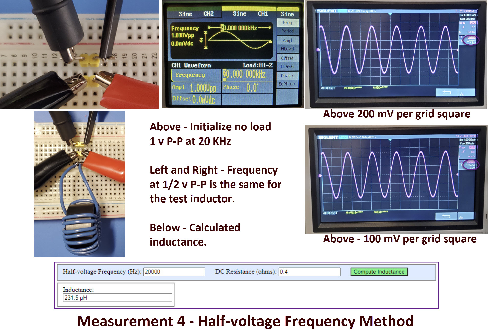
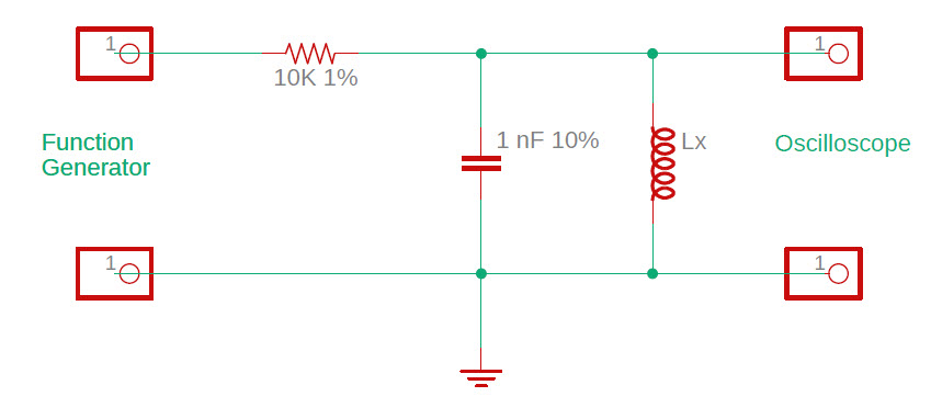
I recalled another method of determining inductance, the half-voltage frequency method, for
which I had made a convenience
calculator.
This recollection caused me to think about one of the assumptions of
the method, namely that the function generator’s output impedance is 50
ohms. The Siglent generator that I was using has the requisite output
impedance (photo left), but I wasn't sure of the attached cable, which
had been changed from the manufacturer-supplied cable at some point in
the past, so I replaced the output cable with a known 50-ohm impedance
lead.
Measurement
torture:
While mildly interesting as a path to improving the precision of a
measurement, the preceding was of
no use in figuring out the unyielding FT87A mix problem.
Frequency measurements were the same to 2 or 3 significant digits,
whether a
single-capacitor was used for the tank circuit, or four. While in the
midst of this perseverative exercise,
I recalled another method of determining inductance, the half-voltage frequency method, for
which I had made a convenience
calculator.
This recollection caused me to think about one of the assumptions of
the method, namely that the function generator’s output impedance is 50
ohms. The Siglent generator that I was using has the requisite output
impedance (photo left), but I wasn't sure of the attached cable, which
had been changed from the manufacturer-supplied cable at some point in
the past, so I replaced the output cable with a known 50-ohm impedance
lead.
Fresh
start:
In one sense starting over is just
another kind of perseveration, but I was curious if the FT87A might
have an inconspicuous marking on it, maybe in the middle somewhere
(obscured by the coil). Also the 50-turn test coil was poorly wound,
loose, unevenly spaced. I
should make a better test coil. The most disturbing part of the
classification problem was not the failure of identifying the mix, but
rather the inconsistent results of measurements. Different methods of
measuring the same thing, whether the thing being measured is length or
weight or inductance, should yield the same approximate
answer.
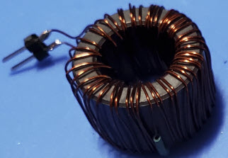
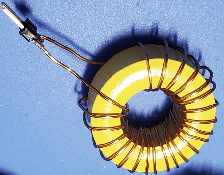
 Stripped of its first test coil, the
ferrite toroid had no hidden inscription on either outside or inside,
and was just one shade of
grey! The chance of its having an identifying mark was a long shot, of
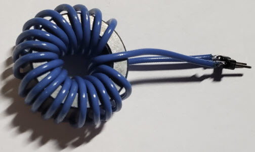
course. For the next suite of tests with this toroid I
wound 20 turns of plastic insulated wire, somewhat more neatly than the
enamel-insulated wire coil had been wound. The plan was to measure the
new coil’s inductance in four different ways, while recording details
at each step. Snapping a cellphone photo at each step is one way to
temper haste.
Stripped of its first test coil, the
ferrite toroid had no hidden inscription on either outside or inside,
and was just one shade of
grey! The chance of its having an identifying mark was a long shot, of
course. For the next suite of tests with this toroid I
wound 20 turns of plastic insulated wire, somewhat more neatly than the
enamel-insulated wire coil had been wound. The plan was to measure the
new coil’s inductance in four different ways, while recording details
at each step. Snapping a cellphone photo at each step is one way to
temper haste.
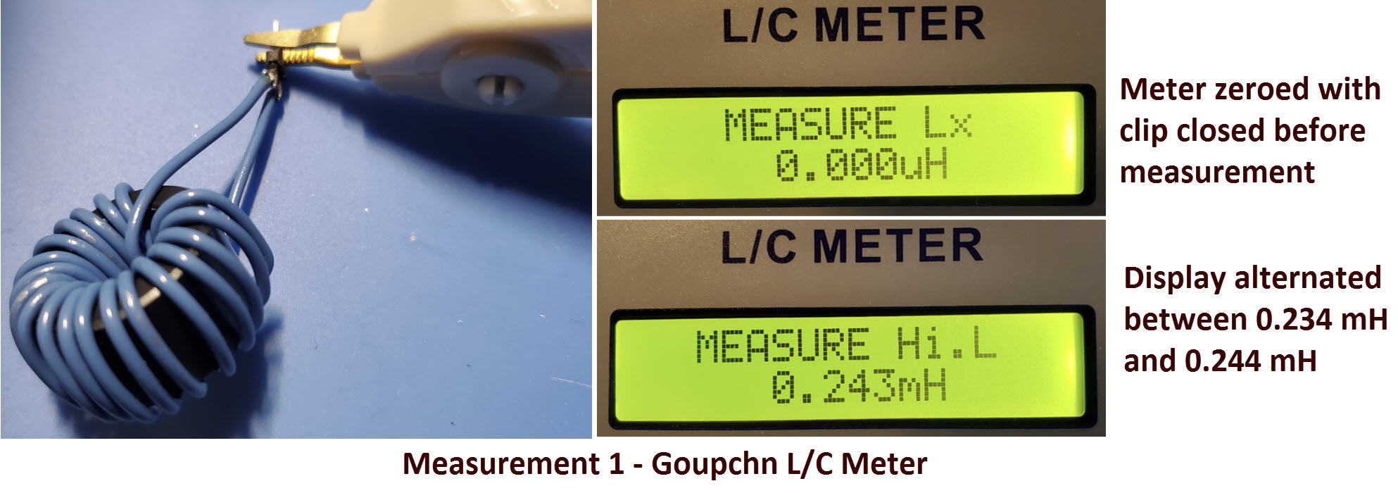
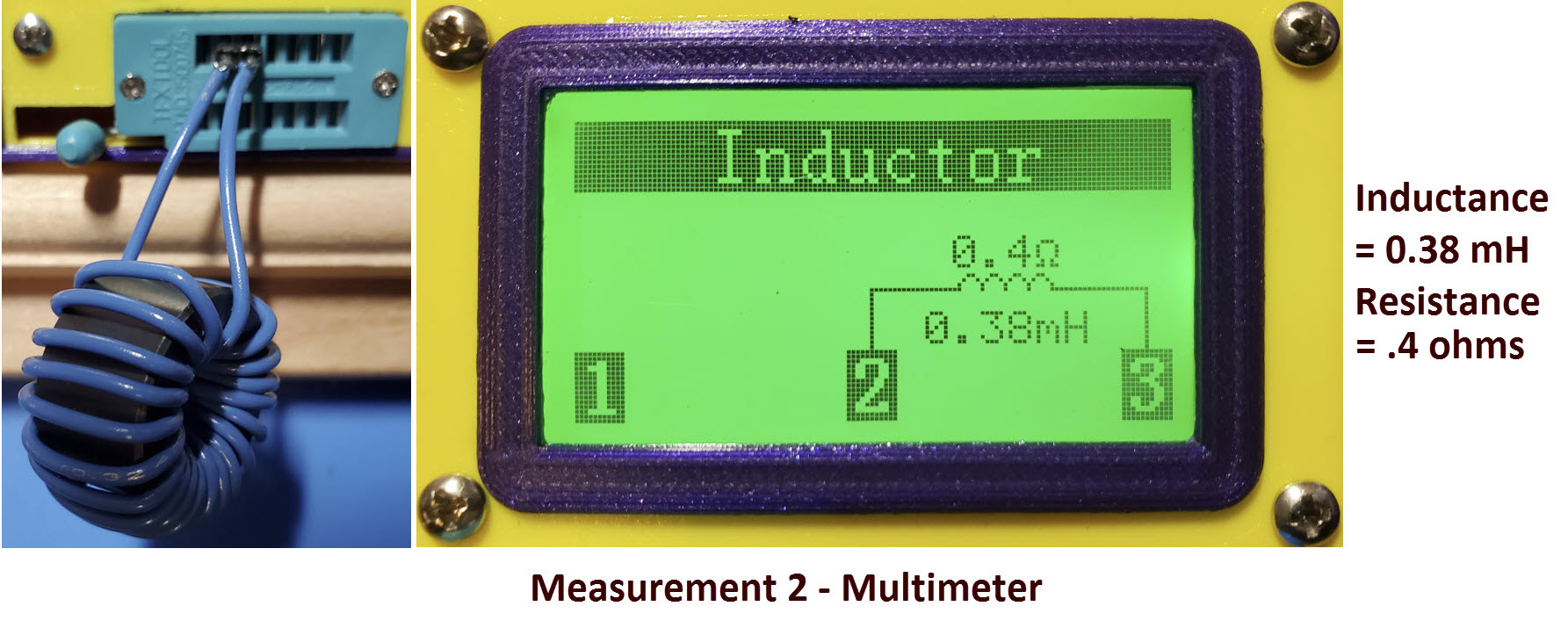
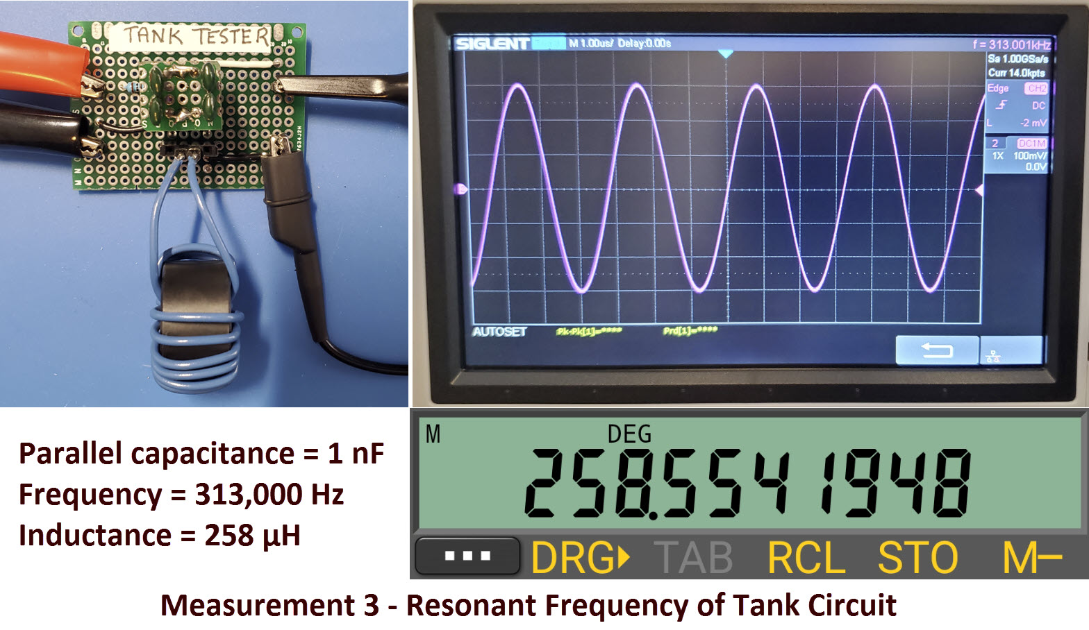
The four measurement procedures can be summarized as 1) Goupchn L/C
meter direct measurement, 2) Multi-meter measurement, 3) Tank circuit
resonant frequency determination, and 4) Half-voltage frequency
measurement. The following is a picture story.
Four Measurements of
Inductance
 What is
it?
What is
it?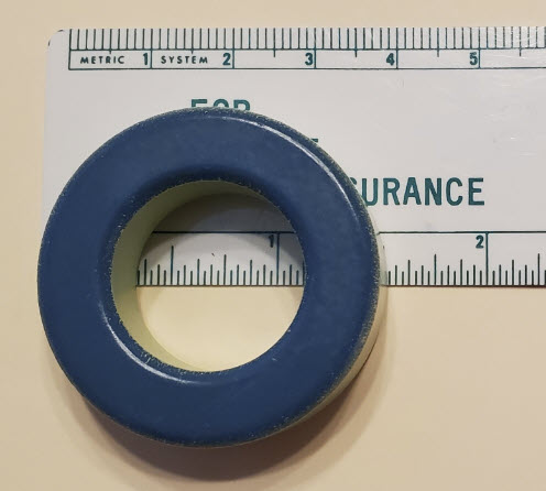 Inches:
The world is metric but for some reason, toroid classification uses
inch measure. First there is an alpha prefix, ‘T’ for toroid and
‘FT’ for guess what. After that comes a number that seems mysterious,
until we learn that it is the outer diameter of the annulus in
hundredths of
an inch.
Thus the blue-green toroid in the illustration is a T157-something
because first,
it is an iron powder (not ferrite) toroid and second, its outer
diameter is 1.57 inches.
Luckily it is not necessary to be
able to measure the diameter to the precision of one-hundredth of
an inch, because the next smaller iron powder toroid is 1.30 inches and
the next larger one is 1.84 inches—according to the mini Ring Core calculator (a
useful and free utility).
Inches:
The world is metric but for some reason, toroid classification uses
inch measure. First there is an alpha prefix, ‘T’ for toroid and
‘FT’ for guess what. After that comes a number that seems mysterious,
until we learn that it is the outer diameter of the annulus in
hundredths of
an inch.
Thus the blue-green toroid in the illustration is a T157-something
because first,
it is an iron powder (not ferrite) toroid and second, its outer
diameter is 1.57 inches.
Luckily it is not necessary to be
able to measure the diameter to the precision of one-hundredth of
an inch, because the next smaller iron powder toroid is 1.30 inches and
the next larger one is 1.84 inches—according to the mini Ring Core calculator (a
useful and free utility). 

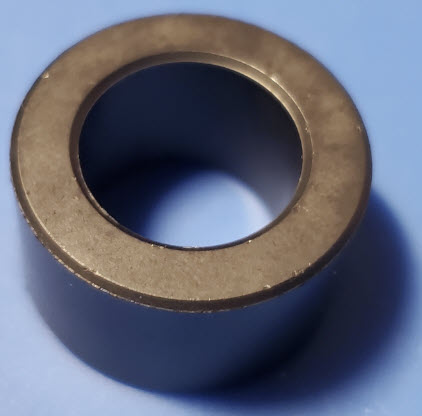
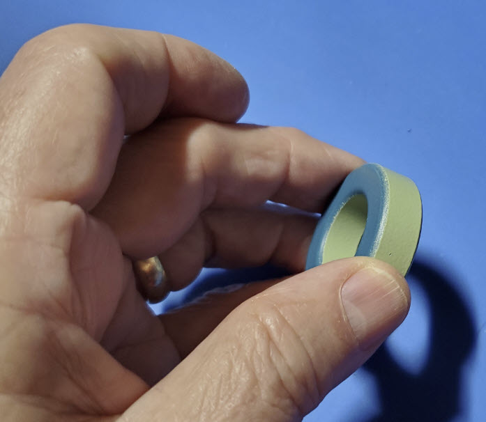
 Ferrite
Toroid:
One of the ferrite toroids in my ‘collection’ has an unusual shape. It
is fatter than most, relative to its diameter. This dimension is
called ‘height’ not width. (For naming this dimension, toroids must
be
imagined lying flat, not in the orientation of a car wheel.)
Ferrite
Toroid:
One of the ferrite toroids in my ‘collection’ has an unusual shape. It
is fatter than most, relative to its diameter. This dimension is
called ‘height’ not width. (For naming this dimension, toroids must
be
imagined lying flat, not in the orientation of a car wheel.)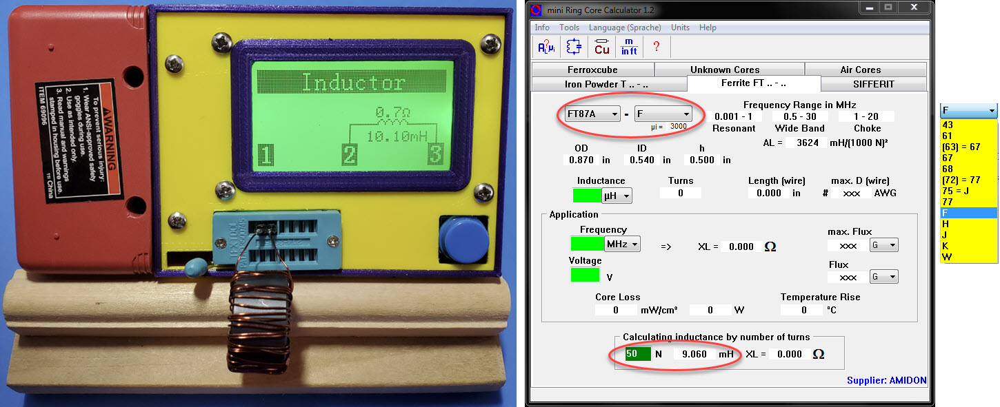
 One
more: I will present one more example, partly because the
toroid is pretty, but also because, for this one, two mix types yield
very similar calculated inductance values; thus correct classification
depends on its color code.
One
more: I will present one more example, partly because the
toroid is pretty, but also because, for this one, two mix types yield
very similar calculated inductance values; thus correct classification
depends on its color code.


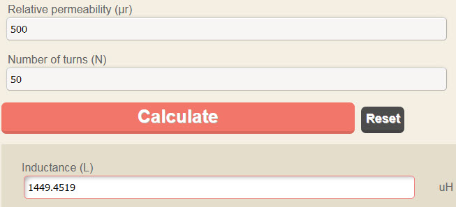
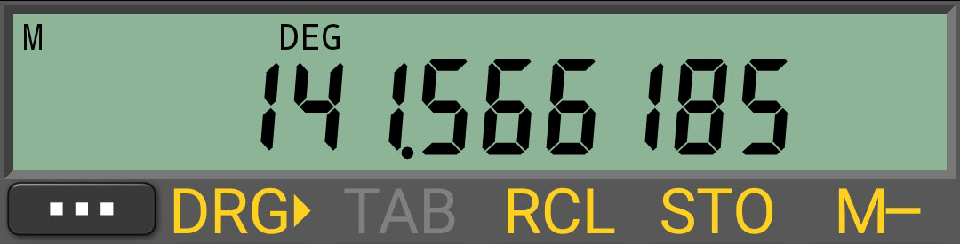 Units are Hertz,
Farads, and Henrys, so there are several 10-something
terms in the calculation. Being careful with the decimal point and
using 423 KHz as the
resonant frequency (the measured value), and 1 nF (10-9
F) for capacitance (its marked and weakly measured value), yields a
calculated inductance of
141.5 μH. This value compares favorably with the multi-tester 0.14 mH
result.
Units are Hertz,
Farads, and Henrys, so there are several 10-something
terms in the calculation. Being careful with the decimal point and
using 423 KHz as the
resonant frequency (the measured value), and 1 nF (10-9
F) for capacitance (its marked and weakly measured value), yields a
calculated inductance of
141.5 μH. This value compares favorably with the multi-tester 0.14 mH
result.
 There were three possibilities for the anticipated outcome of the
resonant frequency test: 1) confirm the original multi-meter result, 2)
confirm the Goupchn meter reading, or 3) ‘none of the above’. Using the
same 1 nF capacitor (same tank circuit) as before, the resonant
frequency was found to be 130 KHz. From this measurement the calculated
inductance is 1.5 mH, which confirms (approximately) the Goupchn
reading.
There were three possibilities for the anticipated outcome of the
resonant frequency test: 1) confirm the original multi-meter result, 2)
confirm the Goupchn meter reading, or 3) ‘none of the above’. Using the
same 1 nF capacitor (same tank circuit) as before, the resonant
frequency was found to be 130 KHz. From this measurement the calculated
inductance is 1.5 mH, which confirms (approximately) the Goupchn
reading.