μBITx
tuned to WWV at 10 MHz
Calibrating
the μBITx (version 5.1) should have
been an easy chore or,
according to some sources,
no chore at all. The
unit is factory aligned, they say. Perhaps so, but WWV does not
transmit at 9,998 KHz, as my μBITx Liquid Crystal Display was
indicating.
Although there is no operating manual
for the unit, a variety of Internet sources describe straightforward
procedures for calibration. Unfortunately, it is not always
clear which sets of directions apply to which firmware versions.
Different
versions
appear to use different calibration methods.
First attempts: Relying
on relevant Internet sources, along with the unit’s Settings menu
prompts, I
attempted to correct the frequency error in my μBITx,
but made no
discernable progress. To
be clear,
I do not fault the manufacturer for this failure. I accept responsibility for not
performing the calibration procedure properly.
Strange things
happened. For example, the unit appeared to key down spontaneously
(or PTT on) at the 10 MHz calibration frequency. This unnerved me. And in
any case I
was at a loss as
to how to tune with the receiver muted. Later
I
asked a fellow μBITx owner if he had experienced any problem
when calibrating his unit. He had not. I am envious of
those who do the right
thing instinctively
when directions are
sparse or menu prompts unclear.
 The hard way:
Perhaps I am naturally inclined to hit upon the
hard way of accomplishing simple things. After hours of
frustration spread over two days I thought to examine the μBITx
sources
to see if they would shed light on the proper or intended calibration
procedure. I was not
sure that the same version numbered sources on github were identical to the
factory-installed firmware, but supposed
that they must be at least similar.
The hard way:
Perhaps I am naturally inclined to hit upon the
hard way of accomplishing simple things. After hours of
frustration spread over two days I thought to examine the μBITx
sources
to see if they would shed light on the proper or intended calibration
procedure. I was not
sure that the same version numbered sources on github were identical to the
factory-installed firmware, but supposed
that they must be at least similar.
From the source code it was clear that
calibrating the unit stores a signed
32-bit correction in EEPROM. This observation suggested the idea of
reading out
the μBITx EEPROM,
and examining the calibration number stored there. First
though,
it seemed prudent to back up the factory
Nano, in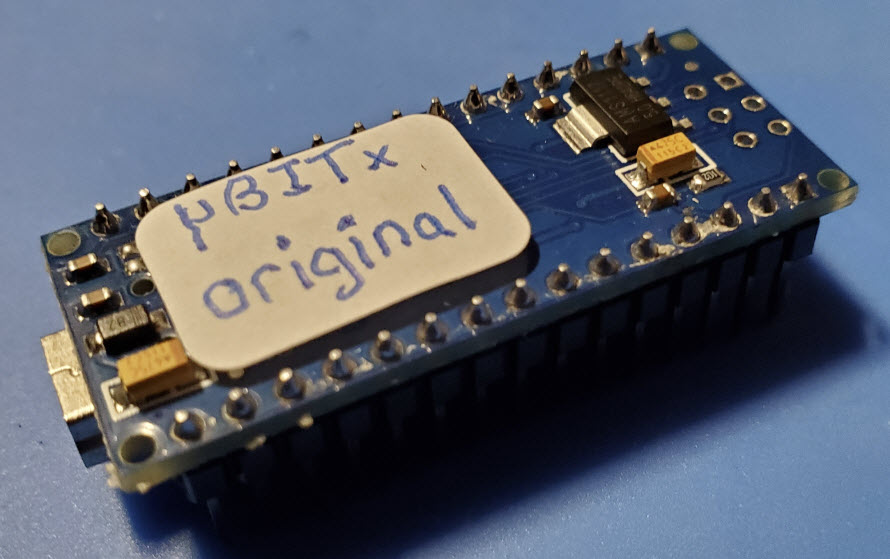 case some mishap were to
render it inoperable. This was probably
unnecessary, as I had previously tested a replacement Nano built from
the compiled github
sources. The
μBITx appeared to work
with this Nano the same as with factory firmware.
But from what is popularly called an ‘abundance of caution’
I decided to duplicate the factory
Nano before fiddling with
it.
case some mishap were to
render it inoperable. This was probably
unnecessary, as I had previously tested a replacement Nano built from
the compiled github
sources. The
μBITx appeared to work
with this Nano the same as with factory firmware.
But from what is popularly called an ‘abundance of caution’
I decided to duplicate the factory
Nano before fiddling with
it.
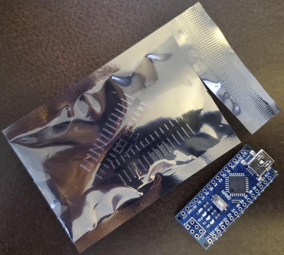
Note: μBITx
Nano pin headers are installed on the component side. Thus the USB
connector and reset button are on the inside of the Raduino assembly
(toward the Si5351 and LCD). If duplicating, be sure to solder pin
headers on the same side as they are on the
original
μBITx
Nano. See photo above right.
The program avrdude.exe is part of the
Arduino IDE distribution and can be used to read or write EEPROM or
flash
memory
to or from a host computer file in Intel
HEX format (or other formats). A tutorial was helpful to
understand
the range of options supported by this very flexible utility.
After experimenting with program parameters I created four small batch
scripts to
wrap calls, mainly because the paths for the configuration
file and
input/output files were long and tedious to type or copy/paste. These
scripts correspond to avrdude parameter values specifying to 1. read
EEPROM,
2. read Flash, 3. write EEPROM, and 4. write Flash. Only
the virtual serial port for the Nano and the input or output
file name vary with different usages.

Example batch script (Read
EEPROM to iHEX file)
After test duplicating and verifying an
unrelated
Nano—one that had been used in a previous project, I copied EEPROM and
flash
from the μBITx factory
Nano to Intel HEX format files. However, on attempting to restore
flash
contents from the stored hex file to a different Nano, avrdude verify
failed.
Furthermore, it was no longer possible to upload any sketch to the
target
Nano from the Arduino IDE without encountering the same
verify failure.
 ‘Unbricking’
(restoring the bootloader)
‘Unbricking’
(restoring the bootloader)
Two bricked Nanos: A
common impediment to efficient problem solving is perseveration. My
first
thought was that the Nano itself was defective, which led to repeating
the flash-copy sequence with another Nano—the last on hand. However, it
soon
became
apparent that the problem related to the
copied bootloader, which was different than the one
the configuration
was expecting. That led to yet another side study, how
to restore
the
Nano bootloader. For this I used the
ArduinoISP sketch (found in the
IDE examples). Carrying
out this well-documented exercise—see
photo above—‘unbricked’
the two Nanos,
but then the realization occurred that simply not overwriting the
bootloader would have prevented the problem in the first place. But
where in flash memory is the Nano bootloader?
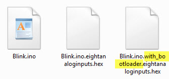
Sketch folder contents
The following trick revealed
the
answer. 1. Load the blink sketch (or any short sketch). 2. Select
‘Export
compiled Binary’ from the IDE Sketch menu. 3. From the same menu choose
the ‘Show Sketch Folder’ option. The folder contents include two
hex files (illustration
above), one of which has
‘with_bootloader’ as part of the file name.
4. Compare the contents of these two files—I used WinMerge
for a side-by-side view. This comparison showed that the Nano’s
bootloader starts at address 0x7E00. It may be possible to
specify an address range to avrdude, but instead I deleted the
bootloader code section from the μBITx flash
hex file before writing
the modified file to a test Nano. Upon
doing this, both write and verify succeeded. EEPROM also loaded to the
test Nano without incident. The final hurdle was to verify the ‘factory
backup’
Nano in the μBITx
itself.
As with the earlier test using compiled sources, this copy appeared to
work the same as the original.
μBITx
EEPROM contents:
Although these paragraphs present an approximate chronology, in
fact I
had
already examined μBITx EEPROM
contents before resolving the flash duplication issue. To do this I
wrote a simple
Arduino
sketch to display EEPROM values corresponding to the same
variables and datatypes
stored by the μBITx
firmware. This one-off
sketch duplicated μBITx
EEPROM address definitions and global variable declarations, and
displayed formatted values via the Serial monitor. It was reassuring
to observe that the Morse keyer speed (stored dot duration) agreed with
the known
value for this setting. However, the Si5353 calibration number was 0.
This was unexpected. Had it always been such, or had I inadvertently
caused 0 to be
stored there in an aborted calibration attempt? Almost surely it was
the latter, but there was no way
to know.
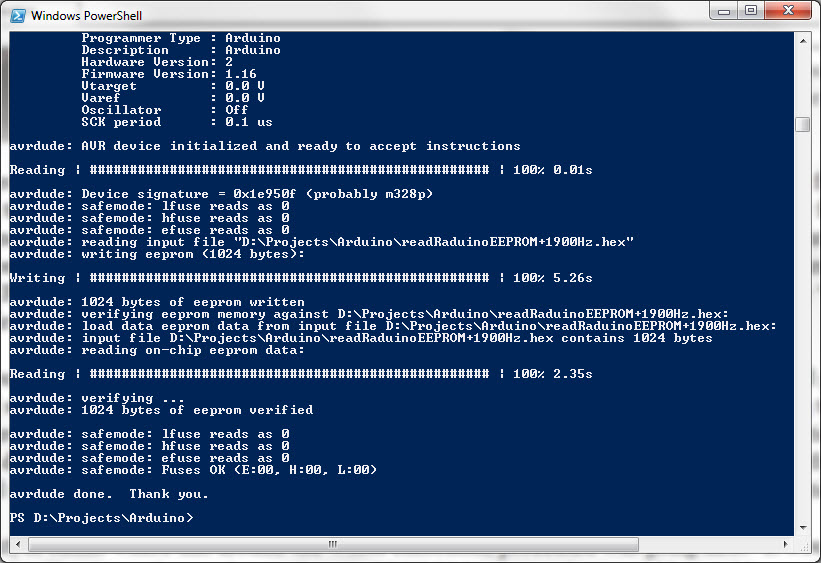
avrdude.exe read/write/verify
By this point it was clear
where this circuitous calibration procedure would be going next. It
would have been possible to construct another simple Arduino sketch to
store (put) trial
calibration values to
EEPROM, whence they
could be read by avrdude and uploaded to the μBITx
Nano, a sort of mirror sketch to the one for displaying μBITx
settings. However, I
thought it would be good to become familiar with
the Intel HEX file format for possible future use,
and maybe to skip a step or two in the potentially repetitious testing
cycle. To that end I created a function to accept an Intel HEX data
record as
input, along with a decimal address, decimal replacement value, and
number of bytes corresponding to the changed value’s datatype, then
generate
a replacement HEX record, and recompute the checksum, etc. For
expediency, I programmed this part in MUMPS, not c++, so there would be
little point
in posting the code here. It is not a difficult exercise in any case.
First convert each test replacement value to hex and reverse the byte
order (left-to-right
is least significant to most significant). The
checksum
algorithm is described in the previously referenced Wikipedia page, and
is also
easy to compute. Finally, slap in the edited hex using a text editor (I
used Notepad++),
and upload with avrdude.
(μBITx variables
of interest do not wrap the 32 byte data records.)
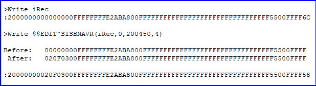
Replacement iHEX record for
decimal test value
From reading or rather skimming the
μBITx
source code I deduced that the value 875 corresponds to a delta of 10
Hz, but wasn’t sure of the sign. Really I was not sure of anything, and
therefore
decided to start with a small number for the EEPROM stored calibration.
This first test value confirmed
the guess that if the
true frequency
is greater than the LCD frequency the sign is positive. After this
edit, the displayed
frequency was about 500
Hz closer to the true
frequency. So I repeated
the procedure twice more until
WWV appeared at 10 MHz on the LCD. (Prior
to each frequency adjustment the BFO was reset to the same value.)
At
this point I switched to a different kind of test. Tuning to a lower
sideband station near 7.150 MHz I observed that voice quality was
clearest (most natural) when the
frequency display was 50 Hz above the even KHz transmit frequency
(verified on a separate receiver). A final tweak of the calibration
number made 40-meter LSB voice stations sound clearest on their
transmit frequencies.
I also tuned in FT8 activity at 7.074 MHz USB.
It feels awkward to
tune an AM
station with a receiver that does not have AM mode. However,
WWV tuned at 10 MHz on the display within
the precision of observation. Voice
announcements were
equally clear on both sidebands at the same display frequency. The
‘final’
calibration number for my μBITx
(Si5351) was +181,000 decimal (2068 Hz), but of course that particular value is meaningless for
any other μBITx.
Not recommended:
As a means of calibration, the EEPROM editing procedure described in
the preceding paragraphs was born of
desperation. Obviously it lacks the simplicity of direct methods, or
the precision of calibrating with instruments, although probably
good
enough for ordinary operation. I had recently recalibrated a different
QRP rig, the CW-only single-band QCX from QRP Labs. That was a piece of
cake. Just hook up the GPS and count cycles between time ticks. Wow! Possibly that
too-easy experience contributed to my impatience with the μBITx,
or my failure to follow the steps for performing calibration properly
via the Setup menu options. I do not recommend calibrating in the
roundabout
way described here. On the other hand these studies were instructive.
They highlighted features of
the microcontroller and programming utilities that may prove useful in
other contexts.
Demo video: ubitx_frequency_calibration.mp4
Project descriptions
on this page are intended for entertainment only.
The author makes no claim as to the accuracy or completeness of the
information presented. In no event will the author be liable for any
damages, lost effort, inability to carry out a similar project, or
to reproduce a claimed result, or anything else relating to a decision
to
use the information on this page.