OR (the long way)
It’s funny how we hit upon new things in
roundabout ways. Some random thought prompted me to do an Internet
search for ‘order finding’. Many of the search results related to
quantum computing and some of these mentioned a logic element called
the ‘Toffoli’ gate. Although I was familiar with the common logic gates
AND, OR, NOT, XOR, etc., I had never heard of Toffoli. At first I had
trouble remembering the name and how to spell it. Then I thought of
‘toffee’ and memorized that the name has two ‘f’s, two ‘O’s, and one
‘l’.
The Toffoli gate is sometimes also
called the C-C-gate, where the letter ‘C’ stands for the word
‘controlled’. However, I will stick with ‘Toffoli’ in this story. It is
easy to understand the specific logic function that the Toffoli gate
performs. The gate has three inputs, which are typically labelled A, B,
and C.
It also has three outputs, whereas common ordinary logic gates have one
output. Toffoli outputs may similarly be labelled P, Q, and R. The
interesting one
is R, because P=A and Q=B, by definition. Output R is like an inverter
(logical NOT), except that it only inverts the C input if both A and B
are true.
In shorthand R = not C if both A and B are true; otherwise R
= C. This statement can be expressed in a simple mathematical way, but
is easier
to understand in words, I think.
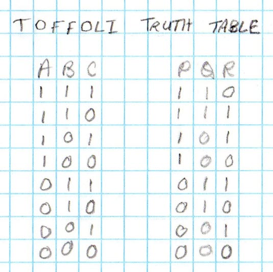
In the table reproduced above, ‘1’
stands for true
and ‘0’ for false,
as is the usual convention. (Similarly, in
electronic logic circuits, + is usually true, and – is false.) Notice
that in the first two rows, both A and B are true and R is not
C, while
in the remaining rows either A or B or both are false, and R = C.
The reason Toffoli gates are of interest
to scientists is due to a property that I will gloss over. They are
invertible. If you know the outputs, you can deduce what the inputs
are. This feature is not shared by some ordinary gates. For example, if
the output of an AND gate is true,
you know all the inputs must have
been true,
but if the output is false,
you cannot deduce which inputs
were false,
since any one of them being false
would render the output
false. One
is inclined to think that of course the Toffoli gate is
invertible, because of the cheat that copies A and B inputs to the P
and Q outputs. That is true, but in the quantum world things are messy,
and
since I don’t understand that world I will have to take the scientists’
word for how being invertible causes entropy to increase, and is
otherwise a commendable thing.
A second crucial property ensures the
Toffoli gate’s interest to researchers: ANY logic
function can be expressed as a combination of Toffoli gates! To prove
this statement it is only necessary to show that AND, OR, and NOT can
be so expressed. It has long been proven that any logic
function can be expressed as a function of these three elementary ones.
NOT is trivial, of course. Let ‘T’ stand for the Toffoli operator: not
C = T(1, 1, C). The other two are also easy, but require more
than one Toffoli gate to implement.
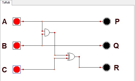
The Toffoli gate can be modelled
using ordinary gates. The Logic
Circuit Designer diagram
above depicts two gates AND (top left)
and XOR (bottom right), and their interconnections. [XOR means either A
or B but not both.] Now,
commonly available 2-input AND gates and 2-input XORs are packaged in
sets of
four. That is to say, each integrated circuit (chip) contains
four gates. So on contemplating the simple diagram above I thought of
assembling four Toffoli gates using just two ICs, with pin headers for
inputs and LEDs
to indicate both input and output states. The idea was that with four
gates
it would be possible to model an AND gate or an OR gate, in other words
to demonstrate the universality claim in an actual circuit.
Not long ago I asked a person who had
taught electronics in a technical college, what sorts of lab exercises
his
students were required to do as part of their coursework. His reply
surprised me. The labs
are all simulations. The students don’t solder anything, or even put
together breadboard circuits. They interact with
circuits using computer software, first constructing diagrams, and
afterward defining parameters that are needed to exercise the circuits,
the same as if they were real. —Logic circuits are particularly easy to
simulate (or so it seems). Pencil and paper suffice to trace logic
levels in simple circuits. They are just algebra, after all.
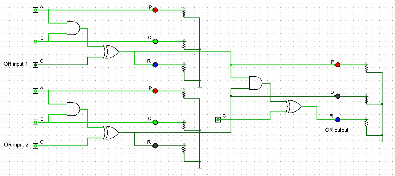
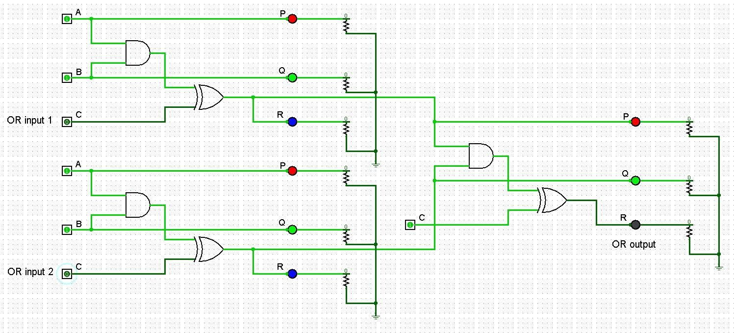
Logism
is a great (free) tool for designing and simulating logic circuits.
After diagramming one Toffoli gate with configurable inputs, it was
possible to copy/paste the composite diagram a couple of times, and
then connect the
three identical gates to function as a single 2-input OR gate. In the
illustration above, the first OR input is
set to false
(0), and the second to true
(1). The output is of course true
(rightmost blue LED). Now, I don’t mean to suggest that a physical
demonstration is more persuasive than the corresponding Logism
simulation, or more persuasive than working through the logic
expression with pencil and paper would be. It is not. However, the
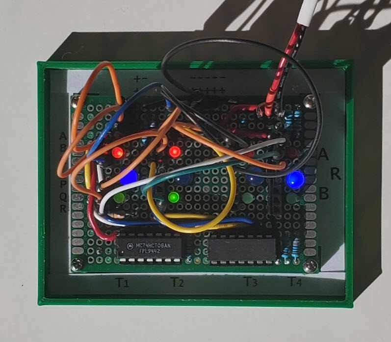
photo at the top of this
page captures what is perhaps a more vivid demonstration of the exact
same circuit as
in the Logism simulation. Even the LED colors are the same!
In the
photo, the third Toffoli gate from left is not involved. Its A, B,
and C inputs were set to false
(black plug-in wires) so that the indicator LEDs
for that gate would be OFF. Each of the two leftmost gates performs R =
T(1, 1, C) = ~C (not C). The final rightmost gate’s A and B inputs
receive
the R outputs of the first two gates, while the C input of this gate is
set to true
(1). If C1 represents input
variable a
and C2 represents variable b, the rightmost
gate preforms T(~a,
~b, 1),
which is the same as a
⋁ b.
Constructing the physical model was fun
but at the same time tedious, in part because I had selected a
prototype
circuit board that has only 24 × 18 holes. Several of the current
limiting resistors
had to be soldered on the underside of the board.
Similarly, about half the connecting wires are on the bottom. The
left IC (type 7408) consists of four AND gates and the right IC (type
7486)
contains four XORs. The four Toffoli gates are arranged in vertical
columns left to right. In each column the topmost 3-hole pin header
corresponds to the inputs A, B, C, and the bottom pin header to the
outputs P, Q, and R. Red LEDs indicate states of the A inputs;
green LEDs the states of B inputs; and blue LEDs (the larger ones)
indicate the ‘R’ output of each gate. Illuminated stands for true, and
not illuminated means false.
Just to be clear, ‘real’ Toffoli gates are not made from ordinary
TTL gates. Best I can tell they are combinations of quantum dots or
some other arcane
sub-microscopic thing. The physical model described above is
just that, a model. By connecting the leftmost blue and yellow wires,
inputs a (C1)
and b (C2),
alternately to 1 (+) and 0 (–) it is possible to demonstrate that in
every case the rightmost blue LED represents the logical OR of a and b, illuminating
when either a
or b or
both are true,
and remaining dark when both are false.
Of course, the
same is more easily demonstrated by toggling pins in Logism. In the
simulation below, both inputs are set to false, which causes
the OR output to be false,
in what surely seems a convoluted way.
Project descriptions on this page are intended for entertainment only.
The author makes no claim as to the accuracy or completeness of the
information presented. In no event will the author be liable for any
damages, lost effort, inability to carry out a similar project, or to
reproduce a claimed result, or anything else relating to a decision to
use the information on this page.