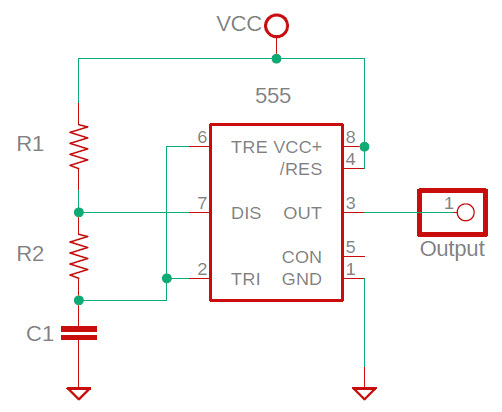
According to Wikipedia
and other sources, the 555 timer is the most popular integrated circuit
ever manufactured, with billions having been sold. Frequency and duty
cycle are
determined by the values of an attached capacitor and resistors, as
explained in the TTL Cookbook and elsewhere. The following calculators
estimate either the frequency that will be generated from given capacitor and resistor values, or the approximate capacitance
needed to achieve a target frequency, given specified test resistor values.
555 Clock Frequency
555 Capacitance
Estimator
Note: Observe 555 minimum and maximum
R/C values (TTL Cookbook, pages 172-173.)
Coax
velocity factor or length
There are several ways to determine
the velocity factor of a known length of coax, or conversely the length
given the velocity factor. Two of these
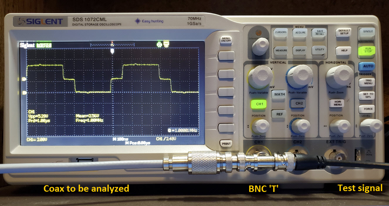
methods are illustrated below. The first is direct measurement of the
round-trip reflection
time for a signal in an unterminated length of coax. The test setup is
simple. A square-wave function generator or oscillator is connected to
an oscilloscope. I use a BNC ‘T’ connector at the oscilloscope input
jack. The ‘unknown’ coax is connected to the other side of the T jack.
Frequency is not critical. Make the
time
scale of the oscilloscope (horizontal axis) sufficiently sensitive to
read reflection
time to within a few nanoseconds. For a 50 foot length of coax, 25 nS per scale division
should work.
Length
Velocity Factor
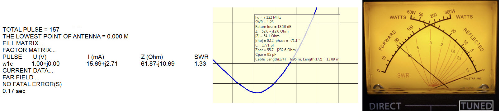
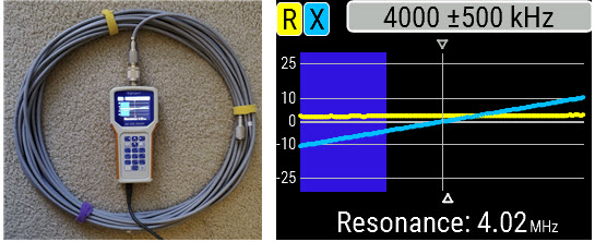
Resonant frequency method
An antenna analyzer can be used to ascertain the resonant frequency of a
length of coax, e.g. at 1/4, 1/2,
etc. wavelengths. Resonant frequency can then be used in a way similar to reflection time,
to estimate length given velocity factor, or conversely to determine velocity factor, given
length. The test setup is shown in the following illustration. (The
illustrated resonance is at 1/4 wavelength.)
Length
Select the appropriate wavelength fraction for the resonance (default
is 1/4λ), or enter a value in the input box if none of the selectable
fractions apply.
Velocity factor
Inductance
from half-voltage frequency
I had ordered an electronics kit and sorted the components
in preparation for assembling the kit. There was one wrong valued
component and one that I wasn't sure about. The questionable component
was an inductor and, while it is simple to test an unknown resistor
with a multi-meter, to measure inductance an LCR meter (which I did not
have at the time) would be needed. Google to the rescue! The page at http://www.dos4ever.com/inductor/inductor.html
presents a simple method to measure an unknown inductance (from a few
to a few hundred μH). Once the procedure described in this resource is
carried out, the mathematical calculation is even simpler, and can be
performed on an ordinary calculator. Even so, why not code the
calculation so that inductors can be measured quickly, with minimal
effort.
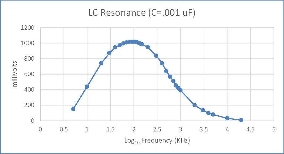
Test example: Assume the inductor has
negligible resistance and that upon carrying out the procedure
described in the above-referenced page, the frequency that resulted in
a half-amplitude reading was 1,175,000 Hz (enter values in Hz, not KHz
or MHz). Entering this value in the frequency box below without commas
(leave the resistance box empty) results in an inductance measure of
3.9 μH, which happens to be the value that the inductor in question
should have had.
If the inductor has a significant internal
resistance (can be measured with an ohmmeter) then enter this value in
the resistance box before clicking ‘compute.’
Note: The experimental
method is fully described at the page linked in the introductory paragraph above.
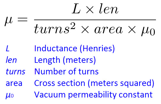
Permeability of a ferrite rod
A 5-pack of ferrite rods of unspecified type or mix were advertised as
suitable for [making] a radio antenna. I thought it should be possible
to ascertain some properties of these rods by first measuring inductance of a
test coil, then using this measured value together with other parameters to compute the material’s permeability:
Magnetic permeability (μ)
Select units for length and diameter.
Select units for inductance.
μ postscript
I am not confident about this calculation. It did not resolve the type of
rods in the 5-pack I’d bought. These rods are each 140 mm in
length. In cross-section they are not exactly round. (See photo -
Are they flattened for gluing?) Outer
diameter (neglecting flattening) is 10 mm and the width between
shaved edges is approximately 8.5 mm. For the μ calculation (which
assumes roundness in this implementation) a middle value (9.25 mm) was entered for diameter.
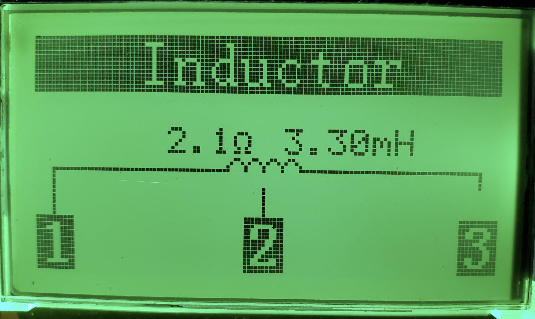
After winding a test coil (240 turns of enameled wire) I measured
inductance in three different ways. The results were in approximate agreement, and for
the calculation I used 3.3 mH. With these values as input, the
calculator gives μ = 95.
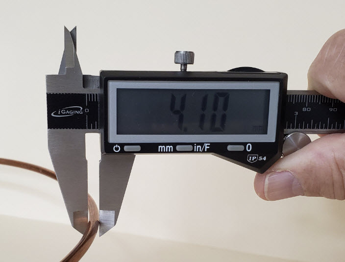
Thinking backwards
However perverse it may be, I have sometimes wanted to calculate
something opposite to the usual way. A recent example was to
compute wire gauge (AWG number) as a function of wire diameter. An
Internet search produced several pages that give formulas, tables, and
calculators for converting wire gauge to diameter, in either English or
metric units, but not the opposite, except of course in the sense that
one can scan a table by eye to identify the row that contains an output
value that is close to the measured diameter. Several sources (for
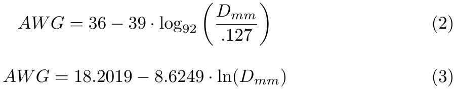
example, this Wikipedia page) give the following formula for wire diameter in millimeters:
The formula reproduced above includes an exponential term, so
the inverse must necessarily contain a logarithm—I thought this as good as
reason as any to refresh my fading memory of logarithms. A detailed
derivation entails several steps, but can be satisfactorily summarized in two. The
first is the direct or immediate inverse of the formula for diameter,
while the second substitutes the natural logarithm for log base 92, and
combines constants in order to simplify the resulting expression.
Formula (3), giving AWG as a function of diameter in
millimeters, has excess precision—more than the original formula. However, the
calculator (below) rounds the answer to
the nearest whole number (i.e., wire gauge number).
Here is another backwards calculation. This one is more a mental
exercise—It doesn’t really merit a calculator, but just for fun. Many
sources
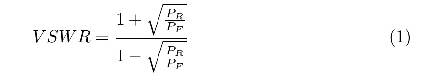
(for example, Wikipedia) give the following
formula for VSWR in terms of reflected power (or, more precisely, the
ratio of reflected
to forward power):
Assume that the ratio of
reflected to forward power is a positive fraction less than 1.
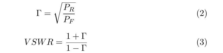
The question is: “For a given VSWR, what proportion of the power is
reflected?” As I said, this is normally a mental calculation, unless
VSWR is extremely high, in which case it is probably too late to have
asked the question! First, simplify the formula with a substitution:
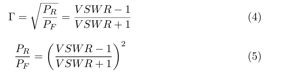
Use ordinary algebra to solve for Γ and then square both sides.
An example will demonstrate how easy it is to calculate reflected power from VSWR. Suppose
VSWR is 3:1.
3 minus 1 is 2. 3 plus 1 is 4. 2/4 = 1/2 and
(1/2)2
= 1/4. Thus, when measured VSWR is 3:1, one fourth the power is
reflected.
Convert Decimal to
Fraction:
Expressing a fraction as a decimal number is easy—simply divide the
numerator by the denominator. However, the reverse problem, to express
a decimal number as a fraction to an acceptable approximation, is less
obvious. To clarify the context, this discussion is about converting
ordinary (short) decimal numbers, such as arise in everyday experience,
to simple fractions. In the United States, tools, such as wrenches and
drill bits and so forth are specified in inches or fractions of an
inch. Thus a digital caliper may display an inch measure
in fractional form for the convenience of selecting the correct
tool. (Metric measurement does not suffer this encumbrance.) The
particular situation that brought the decimal to fraction problem to my
attention had nothing to do with SAE (stands for the Society of
Automotive Engineers), and will be described below, but first I will
explain the calculation itself.
Any finite decimal number is easily converted to a fraction by
putting the decimal digits in the numerator and a corresponding power
of 10 in the denominator, but that is not quite satisfactory.
Generally, a shorter fraction would be preferred, if there is one. As
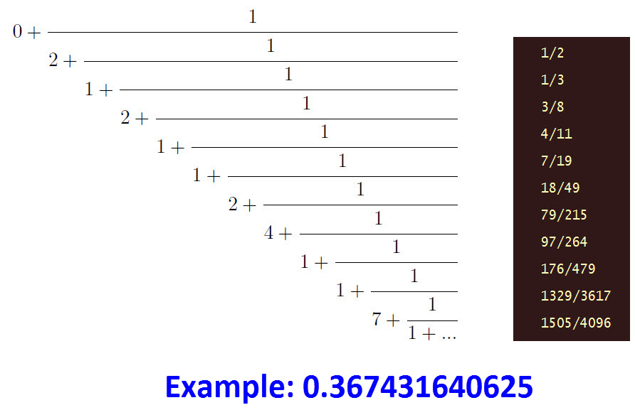
it happens, there is a systematic procedure for converting a decimal
number into what is called a continued fraction,
by breaking the given decimal into an integer part and reciprocal of
the remainder, then iterating the process. At each term, one can
compute a rational fraction represented by the continued fraction up to
that term. Such fractions successively approximate the decimal number.
From
the illustrated example, it seems obvious how to decide where to stop.
Evaluate the fraction at each term, compare to the decimal number, and
decide whether the fraction satisfies the desired precision. In the
calculator below, precision is equal to the length of the input decimal
plus one place. The idea is for the returned fraction to reproduce the
original number up to its length, without a large digit in
the next position. For greater precision simply add
zeros to the end of
the decimal. Now I will briefly describe the exercise that led to
programming this calculator.
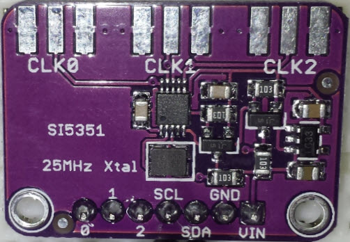
Si5351 A/B/C Programmable Clock Generator The
Si5351* must be one of the most popular chip families in ham radio.
This Silicon
Labs clock generator is found in at least four devices that I
own, including a couple of QRP transceiver kits and the NanoVNA
(vector network analyzer).
An Si5351 breakout board, such as the one pictured on the left, invites
experimentation with an Arduino or other development kit that can
communicate with the clock generator via i2c. The device has
two PLL’s labeled A and B, and three outputs labeled CLK0, CLK1, and
CLK2. Parameters that determine clock outputs are called a ‘frequency
plan’. A desktop computer application from Silicon Labs called
‘ClockBuilder’ can be used to assist in computing frequency plans.
My interest as a hobbyist was to explore Si5351 clock outputs
that were generated from a variety of test inputs. In pursuing this activity I
came
across the problem of converting a decimal number to a
fraction. To explain, the Adafruit Si5351 library for
Arduino includes the methods setupPLL(...) and setupMultisynth(...).
Suppose we have a base frequency and target frequency in mind, and
have computed the ratio of these frequencies as a decimal number.. To
argue a frequency multiplier or divider to one of these library
functions it is necessary to express the decimal part of the
ratio as a fraction (i.e., as numerator and denominator). The
fraction might be as simple as 0/1 or 1/2, but in some cases could be
a longer decimal number. I should stress that this problem does NOT
arise in the context of developing a frequency plan with the aid of
the Silicon Labs ClockBuilder application. It pops up where you want to change an
output frequency
by fiddling either the multisynch or feedback divider, leaving the
other fixed. This is something
that I played with, in learning a little about Si5351 programming.
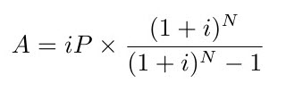
Equal
Payment Amount (Also known as Amortization)
You are given a principal loan amount (P), an
interest rate (i), and a number of equal payments (N). Interest is
expressed as a fraction or proportion per payment. For
example, if the loan is to be paid monthly and the interest is 6% per
year, fractional interest would be 6÷1200 or .005. The divisor
1200 reflects conversion from percent to fraction (÷100) and from
annual to monthly (÷12). The number of payments (N) refers to the total
number over the course of the loan. For example, if payments
are monthly and the loan is for 6 years, N = 6×12 = 72. Let A stand for
the equal payment amount:
Many years ago (i.e., before Internet and before
personal computers) a calculator salesman asked me to program this
problem for his machine, and promised a case of scotch whiskey as
payment. I never saw a drop of scotch, but working out a program for
the problem was reward enough. Back then it wasn’t JavaScript!
Example: Suppose you wish to borrow $25,000.00 at an annual
periodic rate of 6%, and make monthly payments for 6 years. Enter 25000
as a number into the first box (omit the dollar sign and commas), .005
in the second box (see first paragraph above), and 72 in the third box.
Then click the ‘Compute Amount’ button. For these input values the
monthly payment should be $414.32. This amount consists purely of
principal and interest. It does not include any add-on charges that may
be included in a real loan, such as taxes, insurance, and so forth.
The author makes no claim as to the accuracy or completeness of
information presented on this page. In no event will the author be liable for any
damages, lost effort, inability to
reproduce a claimed result, or anything else relating to a decision to
use the calculators or supplemental information on this page.

 I am not confident about this calculation. It did not resolve the type of
rods in the 5-pack I’d bought. These rods are each 140 mm in
length. In cross-section they are not exactly round. (See photo -
Are they flattened for gluing?) Outer
diameter (neglecting flattening) is 10 mm and the width between
shaved edges is approximately 8.5 mm. For the μ calculation (which
assumes roundness in this implementation) a middle value (9.25 mm) was entered for diameter.
After winding a test coil (240 turns of enameled wire) I measured
inductance in three different ways. The results were in approximate agreement, and for
the calculation I used 3.3 mH. With these values as input, the
calculator gives μ = 95.
I am not confident about this calculation. It did not resolve the type of
rods in the 5-pack I’d bought. These rods are each 140 mm in
length. In cross-section they are not exactly round. (See photo -
Are they flattened for gluing?) Outer
diameter (neglecting flattening) is 10 mm and the width between
shaved edges is approximately 8.5 mm. For the μ calculation (which
assumes roundness in this implementation) a middle value (9.25 mm) was entered for diameter.
After winding a test coil (240 turns of enameled wire) I measured
inductance in three different ways. The results were in approximate agreement, and for
the calculation I used 3.3 mH. With these values as input, the
calculator gives μ = 95.