QMX Interface CAT and Rig Control
The beautiful little 5-watt multiband and
multimode1 QMX transceiver
is available from
QRP Labs in
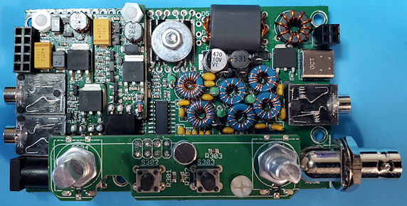
either kit or assembled form. As a kit, the QMX is somewhat challenging
to assemble. Components are densely packed onto PCBs, which in turn fit
tightly into the tiny enclosure. There isn’t much breathing room (see image below). It is
definitely not a project for the first-time kit builder. That said, the
QMX
support community is exceptionally knowledgeable and helpful when
builders encounter problems, as I did on completing initial assembly.
Chances are the problem has been seen before, and regardless, the
engineering and troubleshooting expertise available from
QRPLabs@groups.io is second to none.
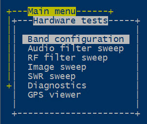
On first powering-on my completed kit all menu
options and
sub-options, of which there are many, were present and likely
working as designed. The receiver had signals on all bands. It was more
sensitive than any previous QRP transceiver kit in my experience, and
had good
selectivity, etc. Subjectively it seemed to perform as well as $1000+
manufactured transceivers. However, there was no RF output from the rig
on key down.
Transmit did not work.
I tried to troubleshoot the transmit problem by
myself at first, and made some progress, but not to the point of
identifying the cause. After a day or two I posted a request for
troubleshooting suggestions. Later I came to find
that many others have posted similar requests to
the community list,
and continue to do so.
Within a few hours a couple of knowledgeable contributors responded
with ideas and suggestions. Then after just one additional helpful
exchange I was
able to pinpoint and correct the problem. Since then my QMX has had no
further issues.
To put the rig through its paces I made a few
contacts on each of the US high bands 20, 17, 15, 12, and 10 meters.
More
than half were DX QSOs. Since this exercise, proving to myself that the
unit works on
all bands, I have used it primarily on 20 meters, except for one or two
scheduled QSOs on other bands. I should mention that there are two
versions of the kit, a low-band version that covers 80 through 20
meters, and the 20 through 10 meter one that I have.
 Serial Interface: A popular feature of the
QMX firmware is a
configuration and diagnostic suite that can be carried out on a
connected computer. Additionally, individual CAT
commands can be manually
entered into a serial terminal emulator that is interfaced to the QMX
via USB. A
subset of common CAT commands is implemented over the virtual serial
channel. USB audio is also supported. Indeed the QMX can operate
FT-8 and other selected digital modes using
WSJT-X or Fldigi or similar connected computer applications.
Serial Interface: A popular feature of the
QMX firmware is a
configuration and diagnostic suite that can be carried out on a
connected computer. Additionally, individual CAT
commands can be manually
entered into a serial terminal emulator that is interfaced to the QMX
via USB. A
subset of common CAT commands is implemented over the virtual serial
channel. USB audio is also supported. Indeed the QMX can operate
FT-8 and other selected digital modes using
WSJT-X or Fldigi or similar connected computer applications.
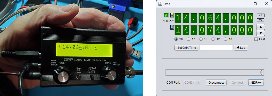
One of the first ‘adventurous’ things that I
tried
with my QMX was to interface it with Ham Radio Deluxe
(HRD). The QMX’s
CAT command subset is
compatible with the Kenwood TS-480 command reference. So that Kenwood
model could be selected
in HRD for demonstration purposes. As would be expected, the HRD
interface experiment succeeded.
Immediately, though, I wanted to make my own custom QMX interface,
implementing
tuning and one or two other basic functions. There was no good reason
to do this other than the pleasure of the undertaking itself.
Although I have little experience with programming in Java, I chose that
language for the project. The goal was to make a graphical user
interface that might
resemble the QMX display. The NetBeans Java IDE provides swing
components
that can be configured to simulate an LED display, along with buttons
and whatever else might be desired. The
right-hand screenshot at the top of this page
shows the interface application at one stage of its development. I
won’t dwell on the development process. It
was necessary to learn a few new things, but I will include a link to
the source code in the final paragraph below, and that code is
reasonably
self-documenting.
IQ mode:
The QMX receiver is an SDR. One of the selections in the QMX menu tree
is called ‘IQ mode’. When
this mode is enabled the QMX conveys in-phase and quadrature samples
via the USB audio left and right stereo channels. After
the CAT interface project was more-or-less complete, I began to look
for a computer SDR application to play with interfacing the QMX
in its IQ mode. I have used multiple SDR applications, but had not
previously downloaded or experimented with SDR++.
One of the IQ ‘Source’
option choices in SDR++ is ‘Audio’ so why not try it?! As
it turned out there was another fortuitously good reason to have
selected SDR++ that I only noticed later.
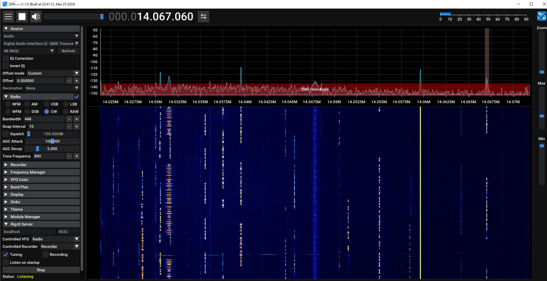
The frequency to which the QMX is tuned determines
the RF range that corresponds to the 48 kHz band of IQ data. At first I
was befuddled,
thinking the QMX frequency should occupy the 0 Hz point in the
IQ band. However, after fiddling with the SDR++ frequency axis and
observing where a generated test signal of known frequency was
received, it became clear that the tuned frequency was at or near the
midpoint of the positive frequencies or 3/4 from the bottom of the 48
kHz band. SDR++ knows about several popular SDRs (e.g., HackRF,
LimeSDR, RTL-SDR, and others). However, it has
no specialized driver for the QMX, thus the
RF frequency corresponding to the QMX audio-source has to be
manually specified.
Now this is not an excuse, or maybe it is. I had
difficulty reading the screen because SDR++ was running on a 4K laptop
adjacent to the QMX bench for interfacing, which caused its text labels
to
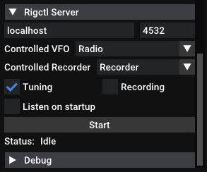
be extremely small.2 In any case, at some point
I happened to notice a ‘Rigctl Server’ that was listed near the bottom
of the microscopic options panel. This led
to the thought of being able to tune SDR++ with the tuning knob in the
QMX (or equivalently to tune via the CAT interface). Whether such a
capability would be of any use remained unclear. It should be mentioned
that at the time of this writing the QMX does not transmit in IQ mode.
I do not want to guess whether a future firmware revision may enable this
capability.
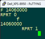 SDR++ identifies as ‘Hamlib Net Rigctl’. I had a small amount of
experience communicating with Hamlib and thought it should be
straightforward to update SDR++’s frequency from the QMX by translating
the CAT format frequency to rigctl format. The reverse should also be
possible. Before attempting to add this functionality to the interface
I used PuTTY to connect to the TCP-IP rigctl server on the same
computer (localhost:4532) in order to test send and receive frequency
commands (see right). From this point it should have been a snap to add
bi-directional frequency updating to the
QMX interface. It was in fact straightforward to update SDR++ from the QMX, but I had trouble
getting the reverse direction to work. As it
happens frequencies covered by the QMX high-band version (14
MHz to 30 MHz) are
all 8 characters in length (units = Hz). In its current iteration, the
interface reads the f rigctl
command response as a fixed length array of 8
characters. I am certain this read can be performed in a more direct or
efficient way,
but for some reason various other tries did not work. The interface
also currently implements a
read timeout, as it would not be good to hang indefinitely on
failing to receive a timely response.
SDR++ identifies as ‘Hamlib Net Rigctl’. I had a small amount of
experience communicating with Hamlib and thought it should be
straightforward to update SDR++’s frequency from the QMX by translating
the CAT format frequency to rigctl format. The reverse should also be
possible. Before attempting to add this functionality to the interface
I used PuTTY to connect to the TCP-IP rigctl server on the same
computer (localhost:4532) in order to test send and receive frequency
commands (see right). From this point it should have been a snap to add
bi-directional frequency updating to the
QMX interface. It was in fact straightforward to update SDR++ from the QMX, but I had trouble
getting the reverse direction to work. As it
happens frequencies covered by the QMX high-band version (14
MHz to 30 MHz) are
all 8 characters in length (units = Hz). In its current iteration, the
interface reads the f rigctl
command response as a fixed length array of 8
characters. I am certain this read can be performed in a more direct or
efficient way,
but for some reason various other tries did not work. The interface
also currently implements a
read timeout, as it would not be good to hang indefinitely on
failing to receive a timely response.
Software:
I make no promises. This application was just something fun to
do. Maybe it will give someone an idea to follow. The Java source code
may be read
as pseudocode, or for working examples of serial or TCP-IP
or file I/O. The file named QMX.jar in the dist
sub-folder is runnable under Windows, provided that the Java runtime
engine (JRE) is installed. Double-click or right click then ‘Open’. To
build the application from source in
NetBeans it is necessary to download and include a custom serial com
library from https://fazecast.github.io/jSerialComm/.
One last warning: My QMX is still working—the interface has
caused it no harm. However, use or experiment at your own risk. A zip
archive of the project may be downloaded from here. Startup options are
documented in the main(...) method’s source code.
Video: IQ mode Demo (2-minute YouTube summary video)
Bi-directional tuning (11-minute raw video, experiments with tuning, calibrated and uncalibrated frequencies, CW and FT8)
AM Demodulation (7½ minutes narrated video demonstrating CAT and rigctl interfaces, as well as demodulating AM in SDR++)
Endnotes
1. Currently CW and digital modes are supported.
However, the unit has a built-in electret microphone and
voice-modulated SSB may be in its future.
2. Later I changed the laptop screen resolution to
half the 4K default, enabling SDR++ to be displayed normally, and also
enabling full-screen video recording of the display (see links at bottom
of page).
Project descriptions
on this page are intended for entertainment only.
The author makes no claim as to the accuracy or completeness of the
information presented. In no event will the author be liable for any
damages, lost effort, inability to carry out a similar project, or
to reproduce a claimed result, or anything else relating to a decision
to
use the information on this page.