On
The Go
 A small
puzzle: The
illustration shows a standard USB data/charging cable, the type that
might be used to transfer photos or music between a computer (the
larger USB-A connector) and an Android cell phone or tablet (the
smaller micro-B
connector). The USB-A plug has four pins, while the micro-B has five.
Two of
the pins on each end are power (Vcc and ground)—that much is obvious.
Two are data (D+ and D−). What then is the other micro connector pin
for, and which pin is it? The answer is easy to find with a quick
Internet search, but I’ll come back to that in a moment.
A small
puzzle: The
illustration shows a standard USB data/charging cable, the type that
might be used to transfer photos or music between a computer (the
larger USB-A connector) and an Android cell phone or tablet (the
smaller micro-B
connector). The USB-A plug has four pins, while the micro-B has five.
Two of
the pins on each end are power (Vcc and ground)—that much is obvious.
Two are data (D+ and D−). What then is the other micro connector pin
for, and which pin is it? The answer is easy to find with a quick
Internet search, but I’ll come back to that in a moment.
One question that popped to mind was how
many wires are in the cable. It should have been obvious that the cable
would have four and not five wires, since one end has only four pins.
But imagining some quasi-magic possibilities I
cut one of these data cables. Indeed there were four wires, not five.
More precisely, the cable I cut had four wires plus a shield, but the
black wire was common with the shield, so there were four separate conductors.
A diagram of the micro-B connector shows
pins labeled Vcc, D-, D+, ID,
and Gnd. The odd-man-out pin is number 4, called ‘ID’. The plot
thickens! How can a pin that is not connected serve any purpose? (I
guessed that ID must stand for identifier.)
It is time to cry ‘uncle’, AKA hit the
search engine. The answer is that the micro-B’s pin 4 does
not always float. Sometimes it is grounded
internally, i.e., inside the connector. I picture this as a blob of
solder between pins 4 and 5, although I’m
sure that’s not how it
really is. The illustration above shows a USB ‘OTG’ cable. ‘OTG’ stands
for ‘On The Go’, a less than informative name, but let’s face
it—marketing rules the world. Pin
4 of the micro-B plug
end of this cable is connected to ground. The other two connectors are
female (USB-A and a micro-B jack).
The purpose of grounding the ID pin is
to bring about a sort of role reversal. Normally when a computer and
cell-phone or tablet are connected, the computer is the ‘host’ and the
cell phone or other device is the peripheral. The host is also known as
the OTG A device, and the connected device as a B. (Here the letters
‘A’ and ‘B’ have nothing to do with the similarly named USB connector
types.) In other words, the OTG A or B designation identifies whether
the device to which the plug connects is a USB host or not.
The connection between pins 4 and 5 can
be verified with an ohmmeter, although it is challenging to make such a
measurement without the aid of an exposed socket. In any case, ‘the proof is
in the pudding’—an Android application that needs to access a USB
device as host will not work unless the connecting plug is of the
correct type. One such application is SDR Touch.
I had exercised this application (the free version) using a
commercially available OTG cable similar to the one pictured above.
Then at some point I thought to construct a breakout version of the
cable, and to use
SDR Touch with this breakout to test my understanding.
When a USB device is connected to a cell
phone or tablet without ancillary power, it tends to drain the battery
more quickly than when nothing is connected. However, when plugged into
a charger the micro-B path in the OTG cable passes 5 volts from the
micro-B jack to both
the micro-B plug and the USB A jack. In this way power from the charger
supplements the battery, retarding its discharge rate.
The annotated
photo above shows the test setup for simulating OTG. My old cellphone
(lower right) no longer has service, but is okay for running apps that
do not depend on the latest Android version. SDR Touch (the application
running on the phone) supports SDRplay
(upper right). That is to
say, a driver is available for SDRplay. The perforated board has
several USB connectors and associated headers. Finally the ribbon wire
is a five-conductor
cable that maps all 5 pins of the micro-B plug to the breakout board
via a plug-in header. With this 5-pin wire it is possible to ground or
unground the ID pin at its distal end.
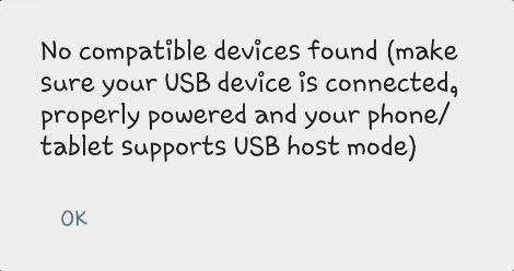 There’s not much
to say about what happens. It is exactly what is expected, an
anti-climax. When the ID pin is floating, the SDRplay driver cannot be
loaded and the message on the left is displayed. When pin 4 is grounded
using the jumper visible in the zoomed ‘detail’ part of the
illustration (upper left), the user is asked whether to accept the
driver that was found and whether to make it the default (right photo).
As far as I can tell, this part does not work properly, as the same
dialog is repeated the next time the application is cold-started. In
other words, the selected driver does not load by default, but it does
load on request and the application works.
There’s not much
to say about what happens. It is exactly what is expected, an
anti-climax. When the ID pin is floating, the SDRplay driver cannot be
loaded and the message on the left is displayed. When pin 4 is grounded
using the jumper visible in the zoomed ‘detail’ part of the
illustration (upper left), the user is asked whether to accept the
driver that was found and whether to make it the default (right photo).
As far as I can tell, this part does not work properly, as the same
dialog is repeated the next time the application is cold-started. In
other words, the selected driver does not load by default, but it does
load on request and the application works.
The annotated illustration above also
shows data pins connected by jumpers from the host-mode plug to the
SDRplay USB-A jack, and power from the charger connection at the bottom
to both the phone and peripheral. The ID pin does not connect anywhere
except to ground at the PCB end of the 5-wire test cable, the
same as if it were connected inside the micro-B plug that attaches to
the cell phone. This demonstration might be considered OTG the hard
way! However, the point was to make the ID pin’s function clear to
myself, in other words to understand what is happening in the OTG
cable, and why.
Demo:
OTG.mp4
Project descriptions on this page are intended
for entertainment only.
The author makes no claim as to the accuracy or completeness of the
information presented. In no event will the author be liable for any
damages, lost effort, inability to carry out a similar project, or
to reproduce a claimed result, or anything else relating to a decision
to
use the information on this page.

